I2C Scanner Tutorial: Find I2C Address on Arduino, ESP32 & ESP8266
If you’ve connected an OLED Display, MPU6050, BME280, RTC module or another I2C device to an Arduino, ESP32 or ESP8266, one of the first things you may need to know is its I2C address.
An I2C Scanner is a simple diagnostic program that scans the I2C bus and reports the addresses of devices that respond.
It is one of the most useful tools for troubleshooting Arduino and ESP32 projects. You can use it to find an unknown I2C address, verify your wiring, detect multiple devices and determine whether an I2C peripheral is responding.
If your project reports “No I2C devices found”, running an I2C Scanner should usually be one of the first troubleshooting steps.
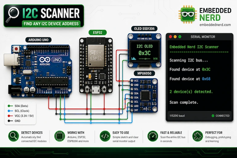
In this tutorial you’ll learn:
- What I2C communication is
- How I2C addresses work
- How an I2C Scanner works
- How to wire I2C devices to Arduino Uno
- How to use an I2C Scanner with ESP32
- How to use an I2C Scanner with ESP8266
- How to find an unknown I2C address
- How to interpret scanner results
- How to troubleshoot “No I2C devices found”
- Common I2C addresses for popular modules
What Is I2C?
I2C (Inter-Integrated Circuit) is a communication protocol commonly used to connect sensors, displays and other peripherals to microcontrollers.
Instead of requiring separate communication lines for every device, I2C allows multiple devices to share the same bus using two main signal lines:
- SDA (Serial Data)
- SCL (Serial Clock)
Multiple sensors, displays and modules can therefore communicate with the same microcontroller using the same SDA and SCL connections.
Popular I2C devices include:
- SSD1306 OLED Display
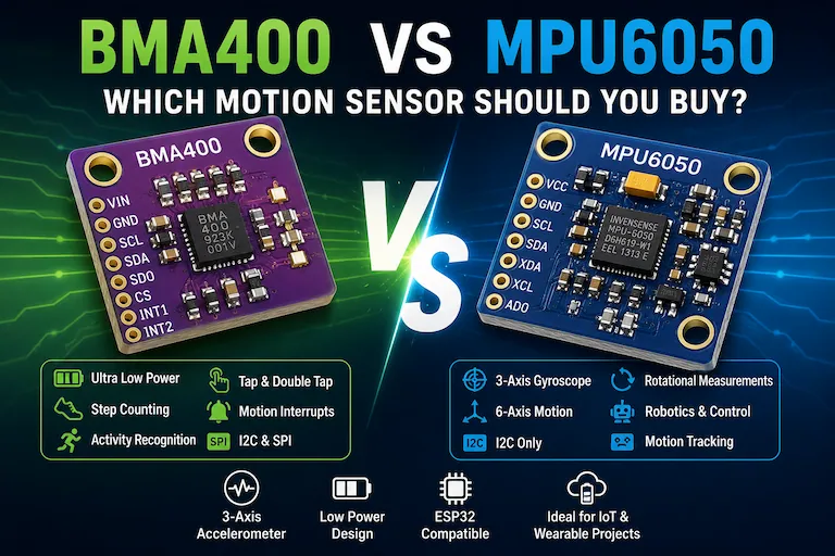
- MPU6050 accelerometer and gyroscope
- BMA400 accelerometer
- BME280 environmental sensor
- BMP280 pressure sensor
- DS3231 Real Time Clock
- PCF8574 I/O expander
- ADS1115 Analog-to-Digital Converter
- LCD displays with I2C backpack
Each device normally needs a unique I2C address on the bus.
How I2C Addresses Work
Every I2C device uses an address that identifies it on the bus.
Addresses are normally written in hexadecimal, such as:
0x3C
0x68
0x76
For example, an SSD1306 OLED commonly uses 0x3C, while an MPU6050 commonly uses 0x68.
However, the actual address can vary depending on the module and its hardware configuration.
Some devices provide address pins or solder jumpers that allow the address to be changed.
This is why using an I2C Scanner is often better than simply assuming the address from a tutorial.
Why Use an I2C Scanner?
An I2C Scanner automatically checks the I2C bus for responding devices.
It can help you:
- Find the I2C address of an unknown device
- Verify SDA and SCL wiring
- Confirm that an I2C device is powered
- Detect multiple I2C devices on the same bus
- Troubleshoot communication problems
- Check a new sensor before writing application code
For example, if an SSD1306 OLED does not display anything, one of the first questions to answer is:
Is the OLED actually responding on the I2C bus?
The scanner can answer that in seconds.
Required Hardware
| Component | Recommended Product | Buy |
|---|---|---|
| ESP32 Development Board | ESP32 DevKit V1 | 🛒 AliExpress |
| MPU6050 Accelerometer & Gyroscope | MPU6050 Accelerometer & Gyroscope | 🛒 AliExpress |
| SSD1306 OLED Display | SSD1306 OLED Display | 🛒 AliExpress |
| Breadboard | Solderless Breadboard | — |
| Male-to-Female Jumper Wires | Jumper Wires | — |
Some links on this page are affiliate links. If you purchase through them, Embedded Nerd may earn a small commission at no additional cost to you. This helps support the website and allows us to continue creating free tutorials and guides. Thank you for your support!
The scanner itself does not require a specific sensor. You can use it with almost any compatible I2C module.
Wiring the I2C Bus
I2C devices normally require four connections:
- VCC
- GND
- SDA
- SCL
When multiple I2C devices are used, the SDA and SCL lines can normally be shared between them.
However, always check the voltage requirements of the specific breakout board.
Important: many modern sensors use 3.3 V logic and are not 5 V tolerant. Do not connect 5 V I2C signals directly to a 3.3 V-only device unless the module provides appropriate level shifting.
Arduino Uno I2C Wiring
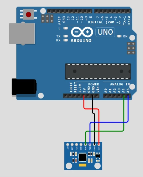
| Arduino Uno | I2C Device |
|---|---|
| 5V or appropriate module supply | VCC |
| GND | GND |
| A4 | SDA |
| A5 | SCL |
On the Arduino Uno, A4 is SDA and A5 is SCL.
The correct supply voltage depends on the I2C module. Always check the module documentation before connecting it to 5 V.
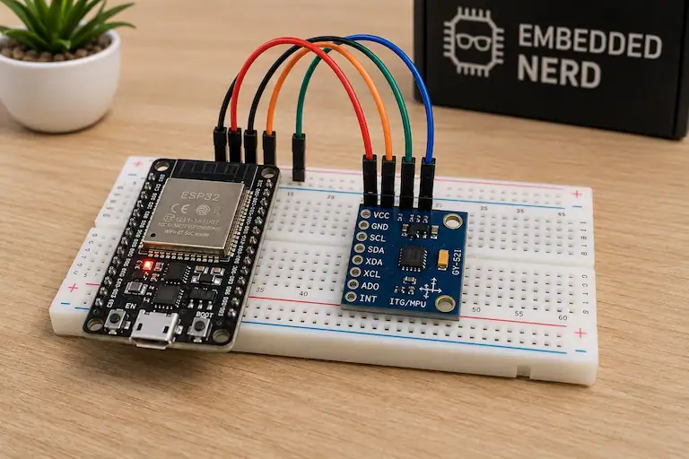
ESP32 I2C Wiring
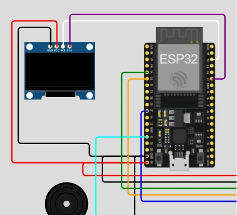
A typical ESP32 development board uses:
| ESP32 | I2C Device |
|---|---|
| 3.3V | VCC |
| GND | GND |
| GPIO21 | SDA |
| GPIO22 | SCL |
GPIO21 and GPIO22 are the common default I2C pins on many ESP32 development boards.
The ESP32 can also use other GPIO pins for I2C when they are configured in software.
ESP8266 I2C Wiring
The ESP8266 also supports I2C, but the SDA and SCL pins depend on the specific board and software configuration.
For this reason, do not automatically use the ESP32 GPIO21/GPIO22 configuration with an ESP8266.
If custom pins are configured in the code, make sure the physical wiring matches those pins.
Before Running the I2C Scanner
Before uploading the scanner sketch, check:
- SDA is connected to SDA.
- SCL is connected to SCL.
- VCC is connected to the correct voltage.
- GND is connected correctly.
- The USB cable supports data.
- The correct board is selected in Arduino IDE.
- The correct COM port is selected.
- The module actually supports I2C.
- The selected SDA and SCL pins match your board.
- There are no address conflicts between connected devices.
These checks can eliminate many common I2C problems before you start debugging the software.
Arduino & ESP32 I2C Scanner Code
The following I2C Scanner uses the Arduino Wire library and can be used with many Arduino-compatible boards, including Arduino Uno, Nano, Mega, ESP32 and ESP8266.
It scans the I2C address range and reports devices that acknowledge the communication request.
/*
   Embedded Nerd
   I2C Scanner Tutorial
   https://embeddednerd.com
*/

#include <Wire.h>

void setup() {

  Wire.begin();

  Serial.begin(115200);

  while (!Serial);

  Serial.println();
  Serial.println("----------------------------");
  Serial.println("Embedded Nerd I2C Scanner");
  Serial.println("----------------------------");
}

void loop() {

  byte error;
  byte address;
  int devices = 0;

  Serial.println();
  Serial.println("Scanning I2C bus...");

  for (address = 1; address < 127; address++) {

    Wire.beginTransmission(address);

    error = Wire.endTransmission();

    if (error == 0) {

      Serial.print("Found device at 0x");

      if (address < 16)
        Serial.print("0");

      Serial.println(address, HEX);

      devices++;
    }

    else if (error == 4) {

      Serial.print("Unknown error at 0x");

      if (address < 16)
        Serial.print("0");

      Serial.println(address, HEX);
    }
  }

  if (devices == 0) {

    Serial.println("No I2C devices found.");

  } else {

    Serial.print(devices);
    Serial.println(" device(s) detected.");
  }

  Serial.println();
  Serial.println("Scan complete.");
  Serial.println("----------------------------");

  delay(5000);
}
How the I2C Scanner Works
The scanner checks I2C addresses one at a time.
The main loop is:
for (address = 1; address < 127; address++)
This checks the commonly used 7-bit I2C address range.
For each address, the scanner starts a transmission:
Wire.beginTransmission(address);
It then ends the transmission:
error = Wire.endTransmission();
If a device acknowledges the address, Wire.endTransmission() returns 0.
The scanner then prints the address.
For example:
Found device at 0x3C
means that an I2C device responded at address 0x3C.
Running the I2C Scanner
Open the Arduino IDE.
Select your board:
Tools > Board
Select the correct serial port:
Tools > Port
Upload the scanner sketch.
Once the upload is complete, open:
Tools > Serial Monitor
Set the baud rate to:
115200
The scanner will then begin checking the I2C bus.
Example I2C Scanner Output
If an SSD1306 OLED and MPU6050 are connected, you might see:
----------------------------
Embedded Nerd I2C Scanner
----------------------------

Scanning I2C bus...

Found device at 0x3C

Found device at 0x68

2 device(s) detected.

Scan complete.
----------------------------
This means that two devices responded.
0x3C is commonly used by SSD1306 OLED displays.
0x68 is commonly used by the MPU6050.
ESP32 I2C Scanner
The same sketch can be used as an ESP32 I2C Scanner.
For a typical ESP32 DevKit:
- GPIO21 > SDA
- GPIO22 > SCL
The scanner can detect devices such as:
- SSD1306 OLED
- MPU6050
- BMA400
- BME280
- DS3231
- ADS1115
If you want to use different I2C pins on the ESP32, initialize them explicitly:
Wire.begin(21, 22);
Replace the pin numbers with the GPIO pins used by your project.
Arduino I2C Scanner
The same scanner can be used as an Arduino I2C Scanner.
On an Arduino Uno:
- A4 > SDA
- A5 > SCL
Other Arduino boards can use different I2C pins, so check the board documentation before wiring your device.
ESP8266 I2C Scanner
The scanner can also be used with ESP8266 boards.
The exact SDA and SCL pins depend on the specific ESP8266 board and your code.
When using custom pins, initialize the Wire library with the pins you are using:
Wire.begin(SDA_PIN, SCL_PIN);
Make sure the wiring matches the pins configured in your program.
Common I2C Device Addresses
The following table lists common addresses found on popular Arduino and ESP32 modules.
| Device | Common Address |
|---|---|
| SSD1306 OLED | 0x3C / 0x3D |
| SH1106 OLED | 0x3C |
| MPU6050 | 0x68 / 0x69 |
| BMA400 | 0x14 / 0x15 |
| BME280 | 0x76 / 0x77 |
| BMP280 | 0x76 / 0x77 |
| DS3231 RTC | 0x68 |
| DS1307 RTC | 0x68 |
| PCF8574 | 0x20–0x27 |
| MCP23017 | 0x20–0x27 |
| ADS1115 | 0x48 |
| INA219 | 0x40 |
| BH1750 | 0x23 |
| VL53L0X | 0x29 |
| PCA9685 | 0x40 |
| SHT31 | 0x44 |
These are common addresses rather than guaranteed values. Always use the address detected by the scanner and verify it against the module documentation.
What If No I2C Devices Are Found?
If the Serial Monitor reports:
No I2C devices found.
don’t immediately assume that the module is faulty.
There are several common causes.
Check SDA and SCL
Make sure:
SDA > SDA
SCL > SCL
Swapping SDA and SCL is one of the most common I2C wiring mistakes.
Check Power
Verify that:
- VCC is connected.
- GND is connected.
- The module is receiving the correct voltage.
Check the I2C Pins
Make sure the pins configured in software match the pins used in your wiring.
This is particularly important with ESP32 and ESP8266 boards.
Test One Device at a Time
If several devices are connected, disconnect them and test one device at a time.
This makes it much easier to identify wiring problems, address conflicts or faulty modules.
Check Pull-Up Resistors
I2C normally requires pull-up resistors on SDA and SCL.
Many breakout boards include them, but not all do.
If several breakout boards are connected, they may also result in too many pull-up resistors being connected in parallel.
Check the Module Documentation
Some modules may:
- use a different I2C address;
- require a different voltage;
- have configurable address pins;
- use SPI instead of I2C;
- require a different wiring configuration.
Troubleshooting “No I2C Devices Found”
If your I2C Scanner repeatedly reports:
No I2C devices found.
use this troubleshooting sequence:
- Disconnect all I2C devices.
- Connect only one device.
- Check VCC and GND.
- Check SDA and SCL.
- Verify the correct I2C pins for your board.
- Upload the scanner again.
- Open the Serial Monitor at 115200 baud.
- Check whether the device is detected.
- If it works, reconnect the other devices one at a time.
Testing one device at a time is usually much faster than trying to troubleshoot several modules simultaneously.
What If the I2C Scanner Finds the Device but My Code Doesn’t?
If the scanner reports:
Found device at 0x3C
but your application cannot communicate with the device, the I2C bus is at least responding at that address.
First, check that your application uses the same address.
For example:
display.begin(SSD1306_SWITCHCAPVCC, 0x3C);
If the scanner reports 0x3D, use:
display.begin(SSD1306_SWITCHCAPVCC, 0x3D);
The scanner confirms that a device responds at an address, but it does not prove that the device is the exact component you expect or that the rest of your application configuration is correct.
OLED Detected but Nothing Appears
If your SSD1306 OLED is detected by the scanner but the display remains blank, check:
- I2C address
- display resolution
- display library
- initialization code
- SDA and SCL wiring
- power supply
For example:
display.begin(SSD1306_SWITCHCAPVCC, 0x3C);
If the scanner reports 0x3D, change the address accordingly.
You can then troubleshoot the OLED application separately from the I2C connection.
See our ESP32 OLED Tutorial: Wiring, Code & Display Guide for a complete OLED example.
Multiple I2C Devices
One of the main advantages of I2C is that multiple devices can share the same SDA and SCL bus.
For example:
| Device | Address |
|---|---|
| SSD1306 OLED | 0x3C |
| MPU6050 | 0x68 |
| BMA400 | 0x14 |
All three can use the same SDA and SCL lines when their addresses and electrical requirements are compatible.
This makes I2C useful for projects such as an ESP32 motion monitor with an accelerometer and OLED display.
What If Two I2C Devices Have the Same Address?
Two devices that respond to the same address can cause communication conflicts.
For example, if two modules both use 0x68, the microcontroller cannot independently select them using only that address.
Possible solutions include:
- Change one device’s address if supported.
- Use an address-selection jumper.
- Use an I2C multiplexer such as the TCA9548A.
- Use separate I2C buses when supported by the microcontroller.
Always check the device documentation before changing an address.
I2C Scanner for MPU6050
An I2C Scanner is particularly useful when setting up an MPU6050.
The MPU6050 commonly responds at:
0x68
or:
0x69
depending on the AD0 pin configuration.
If the scanner cannot detect your MPU6050, check the wiring and power supply before troubleshooting your sensor code.
Once the sensor is detected, continue with our MPU6050 Arduino Guide.
If you need to calibrate the sensor, see our MPU6050 Calibration Guide.
I2C Scanner for BMA400
The BMA400 accelerometer can also be tested with an I2C Scanner.
Depending on the hardware configuration, the BMA400 can use:
0x14
or:
0x15
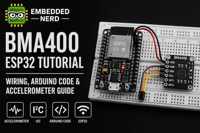
Once the BMA400 is detected, you can continue with our BMA400 ESP32 Tutorial.
I2C Scanner for SSD1306 OLED
SSD1306 OLED displays commonly use:
0x3C
although some modules use:
0x3D
If the scanner detects your OLED, use the detected address in your display initialization code.
You can then continue with our ESP32 OLED Tutorial: Wiring, Code & Display Guide.
Why Every Arduino and ESP32 Maker Should Keep an I2C Scanner
An I2C Scanner is a small utility, but it can save a significant amount of debugging time.
It helps answer three important questions:
- Is my I2C device responding?
- What address is it using?
- Is the problem likely hardware or application code?
Keeping an I2C Scanner sketch available is especially useful when experimenting with new sensors, displays and breakout boards.
GitHub Source Code
The complete I2C Scanner sketch is available in the Embedded Nerd GitHub repository.
Keeping the scanner code available as a standalone utility makes it easy to reuse whenever you connect a new I2C sensor, display or module.
Related Tutorials
If you’re working with I2C devices, these Embedded Nerd tutorials may also be useful:
- MPU6050 Arduino Guide
- MPU6050 Calibration Guide
- BMA400 ESP32 Tutorial
- ESP32 OLED Tutorial: Wiring, Code & Display Guide
An I2C Scanner is particularly useful before starting these projects because it lets you confirm that the hardware is visible on the I2C bus first.
Frequently Asked Questions
What is an I2C Scanner?
An I2C Scanner is a small program that checks I2C addresses and reports devices that respond on the bus.
It is commonly used to identify unknown I2C addresses and troubleshoot communication problems.
How do I find the I2C address of a device?
Connect the device to your Arduino, ESP32 or ESP8266, upload an I2C Scanner and open the Serial Monitor.
The scanner will display the address of every responding device.
For example:
Found device at 0x3C
means that a device responded at 0x3C.
Does an I2C Scanner work with ESP32?
Yes.
The scanner can be used with ESP32 boards. A typical ESP32 DevKit uses GPIO21 for SDA and GPIO22 for SCL.
If you use different pins, configure them explicitly in the Wire library.
Does an I2C Scanner work with Arduino Uno?
Yes.
The Arduino Uno uses A4 for SDA and A5 for SCL.
Other Arduino boards may use different I2C pins.
Does an I2C Scanner work with ESP8266?
Yes.
The Wire library can be used with ESP8266 boards, but the SDA and SCL pins depend on the board and software configuration.
Why does my I2C Scanner say “No I2C devices found”?
Check:
- SDA and SCL wiring
- power supply
- GND connection
- selected I2C pins
- pull-up resistors
- board configuration
- device compatibility
Testing one I2C device at a time can help identify the problem.
Why does my OLED use 0x3D instead of 0x3C?
Both addresses can be used by SSD1306 OLED modules.
The exact address depends on the module configuration.
Use the address reported by the I2C Scanner.
Can multiple I2C devices share the same SDA and SCL pins?
Yes.
Multiple I2C devices can share the same bus as long as their addresses do not conflict and the electrical characteristics of the bus are suitable.
Can two I2C devices have the same address?
They can be connected physically, but if both devices respond to the same address, the microcontroller cannot independently select them using that address.
You may need to change one device’s address or use an I2C multiplexer.
Conclusion
An I2C Scanner is one of the simplest and most useful tools for Arduino, ESP32 and ESP8266 development.
It can quickly identify I2C device addresses, verify that hardware is responding and help diagnose wiring and communication problems.
Whether you’re connecting an SSD1306 OLED, MPU6050, BMA400, BME280, RTC or another I2C peripheral, running an I2C Scanner is often the best first step before debugging the application itself.
Keep this small utility in your Arduino toolkit and use it whenever an I2C device isn’t behaving as expected.
Share on
X Facebook LinkedIn Bluesky
Hardware Used in This Project

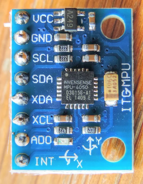
MPU6050 Accelerometer & Gyroscope
MPU6050 6-axis motion sensor combining a 3-axis accelerometer and 3-axis gyroscope with I2C communication.
 Recommended
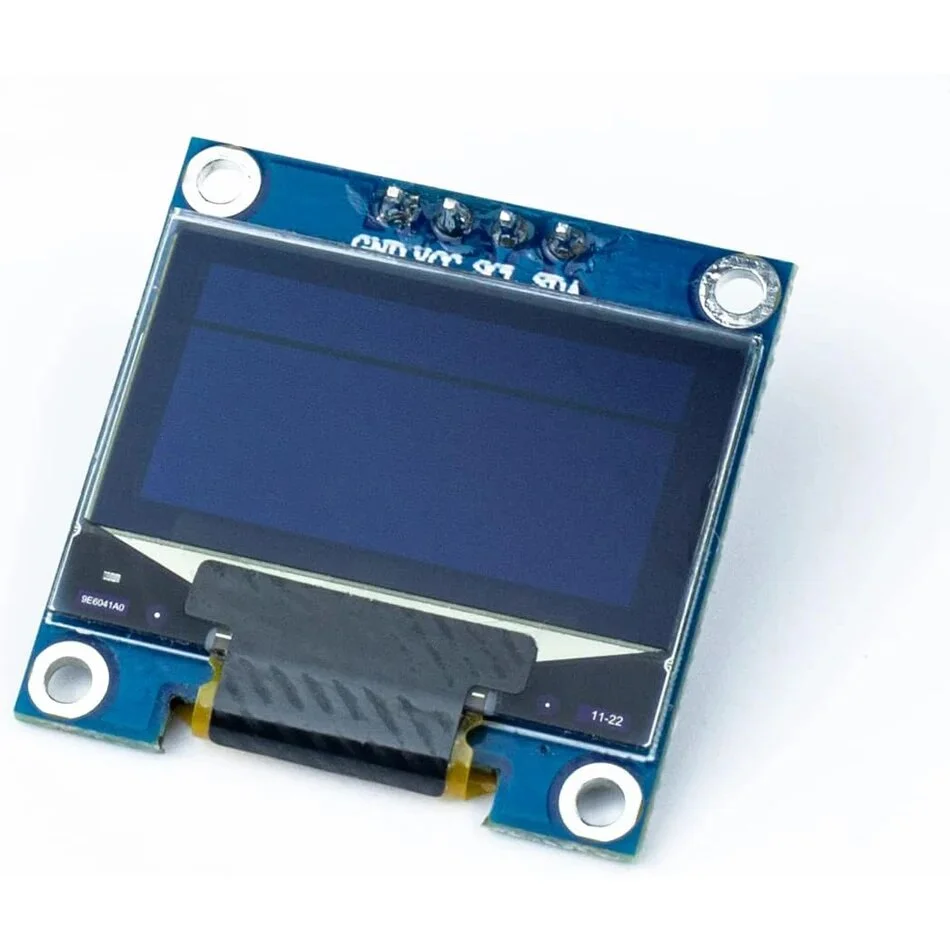
SSD1306 OLED Display
0.96-inch SSD1306 OLED display module with I2C interface for Arduino, ESP32 and Raspberry Pi projects.
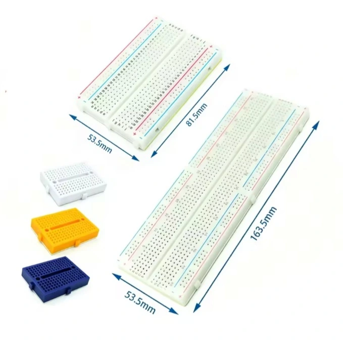
Solderless Breadboard
Reusable solderless breadboard for rapid prototyping of electronic circuits with Arduino, ESP32 and Raspberry Pi.
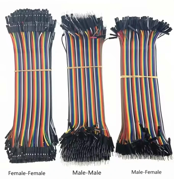
Jumper Wires
Jumper wires for breadboard prototyping with Arduino, ESP32, Raspberry Pi and other embedded development boards.