MPU6050 Calibration Guide: How to Calibrate Accelerometer & Gyroscope
The MPU6050 is a popular motion sensor for Arduino and ESP32 projects, combining a 3-axis accelerometer and 3-axis gyroscope in a single device.
However, the sensor can report small offsets even when it is completely stationary. These offsets can affect motion detection, tilt measurements, orientation calculations, and other applications that depend on accurate sensor readings.
This MPU6050 calibration guide explains how to measure these offsets and compensate for them using Arduino.
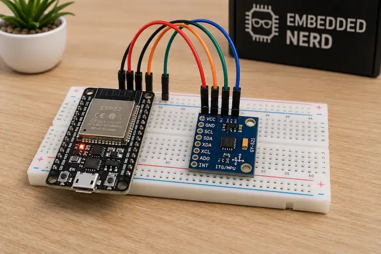
This tutorial includes:
- MPU6050 calibration basics
- Accelerometer and gyroscope offsets
- How to prepare the sensor for calibration
- MPU6050 calibration code
- How to verify the calibration results
- Common calibration problems
- Practical calibration tips
Important: The MPU6050 must remain completely still during calibration. Movement or vibration while collecting samples can produce incorrect calibration values.
If you are new to the MPU6050, start with our MPU6050 Arduino Guide to learn how to connect the sensor, install the required library, and read its accelerometer and gyroscope values.
What Is MPU6050 Calibration?
MPU6050 calibration is the process of measuring the sensor’s offset and using that information to compensate for errors in its readings.
A stationary MPU6050 should produce approximately zero rotational velocity from the gyroscope. When the accelerometer is positioned level, it should also measure approximately zero acceleration on the X and Y axes while detecting Earth’s gravity on the Z axis.
In practice, the raw readings can be slightly different.
For example, a stationary MPU6050 might produce values such as:
Accel X: -120
Accel Y: 340
Accel Z: 16384

Gyro X: 12
Gyro Y: -8
Gyro Z: 3
The exact values depend on the individual sensor and its operating conditions.
Calibration allows us to measure these offsets and compensate for them before using the sensor data in an application.
Accelerometer Offset
The MPU6050 accelerometer measures acceleration along three axes:
- X
- Y
- Z
When the sensor is stationary and approximately level, the expected readings are:
X ≈ 0 g
Y ≈ 0 g
Z ≈ +1 g
The Z axis is different because the accelerometer detects Earth’s gravity.
With the common ±2g accelerometer range, 1g corresponds to approximately 16384 raw counts.
Therefore, a reading such as:
Accel X: 120
Accel Y: -80
Accel Z: 16420
can be normal for a stationary sensor, although the X and Y offsets can still be compensated.
The goal of calibration is not necessarily to make every accelerometer value exactly zero. Instead, the goal is to make the readings match the physical conditions of the sensor as closely as possible.
Gyroscope Offset
The MPU6050 gyroscope measures rotational velocity around the X, Y, and Z axes.
When the sensor is completely stationary, the expected gyroscope readings are approximately:
Gyro X ≈ 0
Gyro Y ≈ 0
Gyro Z ≈ 0
However, a stationary sensor may report small non-zero values because of its inherent bias.
For example:
Gyro X: 15
Gyro Y: -9
Gyro Z: 6
These values indicate that the gyroscope has an offset.
Calibration measures this offset so it can be compensated for when processing the sensor data.
This is particularly important for applications that integrate gyroscope measurements over time, because even a small bias can cause the estimated orientation to gradually move away from the real orientation.
Note: Calibration can reduce the initial gyroscope bias, but it does not completely eliminate long-term gyroscope drift. Temperature changes, sensor noise, and other factors can still affect the readings.
We will cover gyroscope drift separately in a future MPU6050 guide.
Why Does the MPU6050 Need Calibration?
Different MPU6050 modules can have different sensor offsets, even when they use the same sensor chip.
Small measurement errors can affect applications such as:
- Motion detection
- Tilt measurement
- Gesture control
- Robotics
- Self-balancing systems
- Motion-controlled games
- Orientation tracking
Without calibration, a stationary gyroscope may appear to be rotating, while accelerometer offsets can affect calculations based on gravity and tilt.
Calibration provides a better starting point by reducing these measurable offsets.
Required Hardware
| Component | Recommended Product | Buy |
|---|---|---|
| ESP32 Development Board | ESP32 DevKit V1 | 🛒 AliExpress |
| MPU6050 Accelerometer & Gyroscope | MPU6050 Accelerometer & Gyroscope | 🛒 AliExpress |
| Breadboard | Solderless Breadboard | — |
| Male-to-Female Jumper Wires | Jumper Wires | — |
Some links on this page are affiliate links. If you purchase through them, Embedded Nerd may earn a small commission at no additional cost to you. This helps support the website and allows us to continue creating free tutorials and guides. Thank you for your support!
Before You Calibrate
Before starting the calibration process, make sure the MPU6050 is connected correctly and can remain completely stationary.
Follow these steps:
- Place the MPU6050 on a stable surface.
- Keep the sensor in the same orientation during the entire calibration process.
- Make sure the jumper wires are firmly connected.
- Power the Arduino or ESP32 and allow the sensor a few seconds to settle.
- Do not touch the sensor while calibration samples are being collected.
- Avoid surfaces affected by vibration or movement.
- Keep the sensor away from sources of mechanical vibration.
The calibration process relies on collecting multiple measurements while the sensor is stationary.
If the sensor moves during this process, the program may interpret that movement as part of the sensor’s normal offset and calculate incorrect calibration values.
For the best results, place the MPU6050 on a solid, stable surface and avoid touching the breadboard or sensor until calibration is complete.
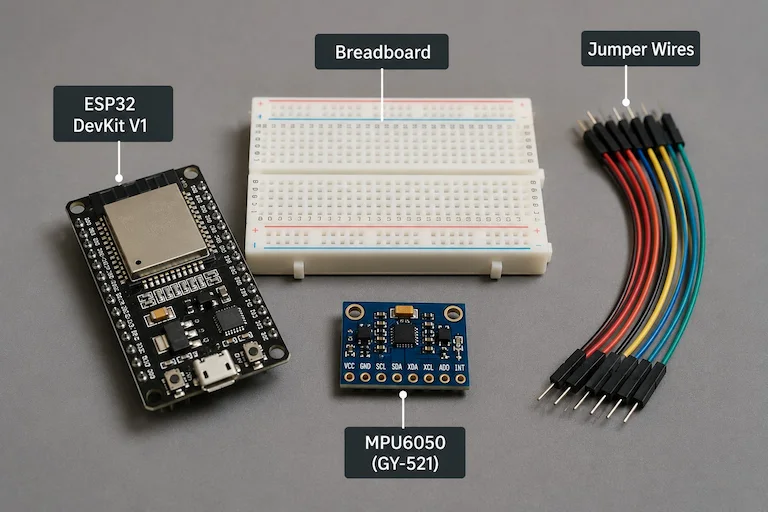
MPU6050 Wiring
The MPU6050 communicates with the microcontroller using the I2C interface.
For Arduino Uno and Nano, the standard I2C connections are:
Arduino Uno / Nano Connections
| MPU6050 Pin | Arduino Uno / Nano |
|---|---|
| VCC | 5V |
| GND | GND |
| SDA | A4 |
| SCL | A5 |
The important I2C connections are:
- SDA — I2C data line
- SCL — I2C clock line
- VCC — Power
- GND — Ground
The default I2C address of most MPU6050 modules is 0x68.
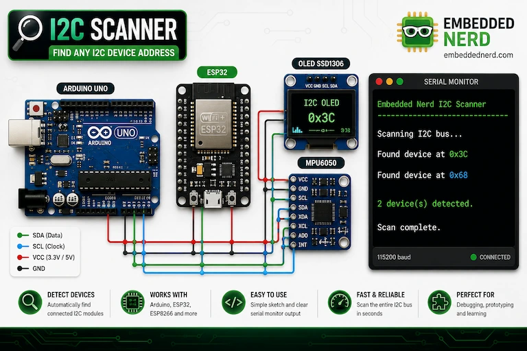
If your MPU6050 is not detected, use our I2C Scanner Tutorial to check the I2C address and verify the connection.
Wiring Note: MPU6050 breakout boards can differ in their power requirements. Check the specifications of your particular module before connecting VCC.
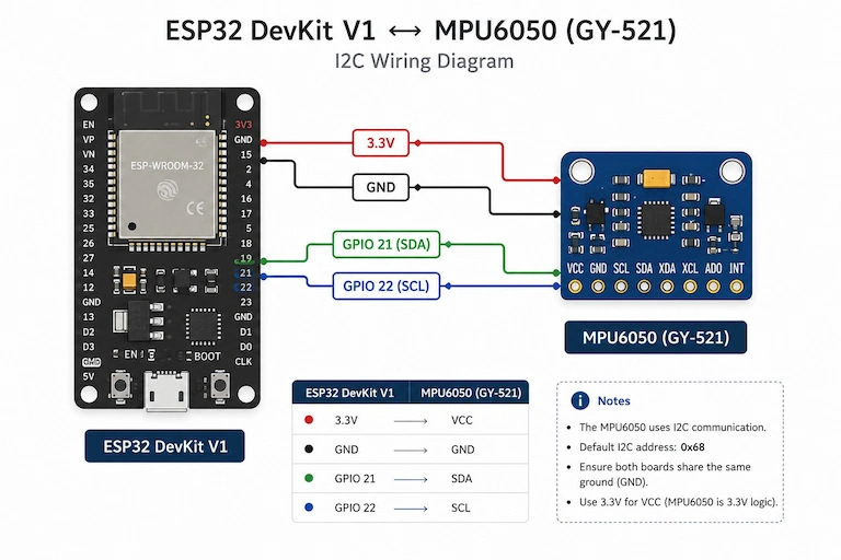
ESP32 Connections
The MPU6050 can also be used with an ESP32.
On a typical ESP32 DevKit, the default I2C pins are:
| MPU6050 Pin | ESP32 DevKit V1 |
|---|---|
| VCC | 3.3V |
| GND | GND |
| SDA | GPIO 21 |
| SCL | GPIO 22 |
The exact I2C pins can be changed in software, so check your particular ESP32 board if you are using a different model.
For the calibration code in this guide, the same MPU6050 library interface used by the existing MPU6050 Arduino Guide is used.
Install the MPU6050 Library
The calibration code uses the same MPU6050 library interface used in our existing MPU6050 tutorial.
If you already followed the MPU6050 Arduino Guide, you can use the same library installation.
Arduino IDE Steps
Open the Arduino IDE and go to:
Sketch → Include Library → Manage Libraries
Search for:
MPU6050
Install a compatible MPU6050 library that provides the MPU6050.h header and the functions used in this tutorial.
The code uses:
#include <Wire.h>
#include <MPU6050.h>
The same library interface is used by the existing Embedded Nerd MPU6050 example, including mpu.initialize() and getMotion6().
How MPU6050 Calibration Works
The calibration process is based on a simple principle:
- Initialize the MPU6050.
- Keep the sensor completely still.
- Read many accelerometer and gyroscope samples.
- Calculate the average value for each axis.
- Determine the sensor bias.
- Subtract the bias from future readings.
- Verify the corrected values.
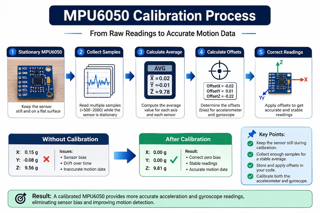
Using many samples is important because a single sensor reading can contain noise.
For example, the gyroscope might produce:
12
14
11
13
12
Even though the sensor is not moving, the readings are not identical.
Averaging many samples produces a more stable estimate of the sensor’s stationary bias.
Gyroscope Calibration
When the MPU6050 is stationary, the ideal gyroscope output is approximately zero on all three axes:
Gyro X ≈ 0
Gyro Y ≈ 0
Gyro Z ≈ 0
If the average stationary readings are:
Gyro X = 12
Gyro Y = -8
Gyro Z = 5
these values represent the approximate gyroscope bias.
Future readings can be corrected by subtracting these values.
For example:
Corrected Gyro X = Raw Gyro X - Gyro X Offset
The same principle applies to the Y and Z axes.
Accelerometer Calibration
The accelerometer requires slightly more care because gravity is part of the measurement.
When the sensor is level and stationary:
Accel X ≈ 0
Accel Y ≈ 0
Accel Z ≈ +1g
At the ±2g sensitivity setting, +1g corresponds to approximately 16384 raw counts.
Therefore, if the measured average is:
Accel X = 120
Accel Y = -80
Accel Z = 16420
the bias can be considered approximately:
Accel X Bias = 120
Accel Y Bias = -80
Accel Z Bias = 16420 - 16384
or:
Accel X Bias = 120
Accel Y Bias = -80
Accel Z Bias = 36
The corrected readings are then calculated by subtracting the corresponding bias.
Important: This guide focuses on practical single-position offset calibration. A more advanced multi-position accelerometer calibration can also compensate for scale and axis-related errors and will be covered separately.
MPU6050 Calibration Code
The following sketch collects 2000 readings while the MPU6050 is completely stationary.
It calculates the average accelerometer and gyroscope readings and then uses those values as software calibration offsets.
The sketch continues running after calibration so you can immediately see the corrected sensor readings.
// =====================================================
// Embedded Nerd - MPU6050 Calibration Guide
// https://embeddednerd.com
// =====================================================

#include <Wire.h>
#include <MPU6050.h>

MPU6050 mpu;

const int NUM_SAMPLES = 2000;
const int GRAVITY_1G = 16384;

// Calibration offsets
long accelXOffset = 0;
long accelYOffset = 0;
long accelZOffset = 0;

long gyroXOffset = 0;
long gyroYOffset = 0;
long gyroZOffset = 0;

void calibrateMPU6050() {

  long accelXSum = 0;
  long accelYSum = 0;
  long accelZSum = 0;

  long gyroXSum = 0;
  long gyroYSum = 0;
  long gyroZSum = 0;

  Serial.println("Keep the MPU6050 completely still.");
  Serial.println("Starting calibration in 3 seconds...");

  delay(3000);

  Serial.println();
  Serial.println("Collecting calibration samples...");

  for (int i = 0; i < NUM_SAMPLES; i++) {

    int16_t ax, ay, az;
    int16_t gx, gy, gz;

    mpu.getMotion6(&ax, &ay, &az, &gx, &gy, &gz);

    accelXSum += ax;
    accelYSum += ay;
    accelZSum += az;

    gyroXSum += gx;
    gyroYSum += gy;
    gyroZSum += gz;

    delay(2);
  }

  long accelXAverage = accelXSum / NUM_SAMPLES;
  long accelYAverage = accelYSum / NUM_SAMPLES;
  long accelZAverage = accelZSum / NUM_SAMPLES;

  long gyroXAverage = gyroXSum / NUM_SAMPLES;
  long gyroYAverage = gyroYSum / NUM_SAMPLES;
  long gyroZAverage = gyroZSum / NUM_SAMPLES;

  // Accelerometer bias.
  // X and Y should be approximately 0.
  // Z should be approximately +1g when the sensor is level.
  accelXOffset = accelXAverage;
  accelYOffset = accelYAverage;
  accelZOffset = accelZAverage - GRAVITY_1G;

  // Gyroscope bias.
  // All three axes should be approximately 0 when stationary.
  gyroXOffset = gyroXAverage;
  gyroYOffset = gyroYAverage;
  gyroZOffset = gyroZAverage;

  Serial.println();
  Serial.println("Calibration complete.");
  Serial.println();

  Serial.println("Accelerometer Offsets:");
  Serial.print("X: ");
  Serial.println(accelXOffset);
  Serial.print("Y: ");
  Serial.println(accelYOffset);
  Serial.print("Z: ");
  Serial.println(accelZOffset);

  Serial.println();

  Serial.println("Gyroscope Offsets:");
  Serial.print("X: ");
  Serial.println(gyroXOffset);
  Serial.print("Y: ");
  Serial.println(gyroYOffset);
  Serial.print("Z: ");
  Serial.println(gyroZOffset);

  Serial.println();
}

void setup() {

  Serial.begin(115200);

  Wire.begin();

  mpu.initialize();

  if (!mpu.testConnection()) {
    Serial.println("MPU6050 connection failed.");
    while (1);
  }

  Serial.println("MPU6050 connected successfully.");
  Serial.println();

  calibrateMPU6050();
}

void loop() {

  int16_t ax, ay, az;
  int16_t gx, gy, gz;

  mpu.getMotion6(&ax, &ay, &az, &gx, &gy, &gz);

  long calibratedAx = ax - accelXOffset;
  long calibratedAy = ay - accelYOffset;
  long calibratedAz = az - accelZOffset;

  long calibratedGx = gx - gyroXOffset;
  long calibratedGy = gy - gyroYOffset;
  long calibratedGz = gz - gyroZOffset;

  Serial.print("Accel: ");
  Serial.print(calibratedAx);
  Serial.print(" | ");
  Serial.print(calibratedAy);
  Serial.print(" | ");
  Serial.print(calibratedAz);

  Serial.print("    Gyro: ");
  Serial.print(calibratedGx);
  Serial.print(" | ");
  Serial.print(calibratedGy);
  Serial.print(" | ");
  Serial.println(calibratedGz);

  delay(500);
}
Try the MPU6050 Calibration in Wokwi
You can run the complete calibration project directly in Wokwi.
How the Calibration Code Works
Collecting Sensor Samples
The number of calibration samples is defined here:
const int NUM_SAMPLES = 2000;
The program then repeatedly reads the six sensor values:
mpu.getMotion6(&ax, &ay, &az, &gx, &gy, &gz);
Each reading contains:
- Accelerometer X
- Accelerometer Y
- Accelerometer Z
- Gyroscope X
- Gyroscope Y
- Gyroscope Z
The readings are added to separate totals and averaged after all samples have been collected.
Calculating the Average
For each axis, the program calculates:
Average = Sum of samples / Number of samples
Using many readings reduces the influence of short-term sensor noise.
Calculating the Gyroscope Offsets
The gyroscope should read approximately zero when the sensor is stationary.
If the average readings are:
Gyro X = 12
Gyro Y = -8
Gyro Z = 5
these values become the software offsets.
A future reading is corrected using:
Corrected Gyro X = Raw Gyro X - Gyro X Offset
For example:
Raw Gyro X = 15
Gyro X Offset = 12

Corrected Gyro X = 3
Calculating the Accelerometer Offsets
The accelerometer uses a known reference: Earth’s gravity.
When the sensor is level, the Z axis should be approximately 1g.
At ±2g:
1g ≈ 16384
Therefore:
Accel Z Offset = Average Z - 16384
The corrected value is then:
Corrected Z = Raw Z - Z Offset
This allows the Z axis to retain the gravity measurement instead of incorrectly forcing it to zero.
Applying the Offsets
The offsets are stored in variables while the program is running.
For each new sensor reading, the calibration values are subtracted:
long calibratedGx = gx - gyroXOffset;
long calibratedGy = gy - gyroYOffset;
long calibratedGz = gz - gyroZOffset;
The same approach is used for the accelerometer.
This is software compensation rather than changing the MPU6050’s internal factory-trim registers.
That makes the example easier to understand and avoids depending on library-specific offset-register behavior.
Calibration Output
After calibration, the Serial Monitor will show the calculated offsets.
A typical result might look like:
MPU6050 connected successfully.

Keep the MPU6050 completely still.
Starting calibration in 3 seconds...

Collecting calibration samples...

Calibration complete.

Accelerometer Offsets:
X: 120
Y: -80
Z: 36

Gyroscope Offsets:
X: 12
Y: -8
Z: 5
The exact numbers will be different for every MPU6050.
The important point is that the sensor should remain completely stationary while these values are being calculated.
After calibration, the program starts printing corrected readings.
For example:
Accel: 15 | -12 | 16390    Gyro: 1 | -2 | 0
Accel: 8 | -18 | 16384     Gyro: 0 | -1 | 1
Accel: 21 | -7 | 16391     Gyro: -1 | 1 | 0
Small variations are normal because the sensor still contains measurement noise.
How to Verify MPU6050 Calibration
Calculating offsets is only part of the calibration process.
You should also verify that the corrected readings behave as expected.
Test 1: Keep the Sensor Completely Still
Place the MPU6050 on a stable surface and leave it untouched.
The gyroscope readings should remain close to zero:
Gyro X ≈ 0
Gyro Y ≈ 0
Gyro Z ≈ 0
Small fluctuations around zero are normal.
Test 2: Check the Accelerometer
Place the MPU6050 approximately level.
At the ±2g setting, the corrected accelerometer should be approximately:
Accel X ≈ 0
Accel Y ≈ 0
Accel Z ≈ 16384
The exact values will fluctuate slightly.
If the board is tilted, the gravity vector is distributed differently between the axes, so the readings will change.
Test 3: Rotate the Sensor
Slowly rotate the MPU6050 around each axis.
The corresponding gyroscope value should change while the sensor is moving.
When the movement stops, the gyroscope readings should return close to zero.
Test 4: Return the Sensor to Its Original Position
After rotating the sensor, return it to the same position used during calibration.
The accelerometer readings should return approximately to their previous values.
The gyroscope should again remain close to zero while the sensor is stationary.
How Accurate Should MPU6050 Calibration Be?
There is no single value that defines a perfectly calibrated MPU6050.
Small variations are normal because the sensor contains noise and its measurements can change with environmental conditions.
The goal is to reduce systematic offset and obtain stable readings suitable for your application.
For example, a gyroscope that fluctuates slightly around zero can be normal:
-2
0
1
-1
2
0
A persistent value such as:
25
26
24
27
25
indicates a much larger bias and may justify recalibration.
Calibration quality can also be affected by:
- Sensor temperature
- Mechanical vibration
- Power supply
- Sensor orientation
- Number of samples
- Movement during calibration
- Individual sensor characteristics
For applications that require higher accuracy, a simple offset calibration may not be sufficient.
A more advanced accelerometer calibration can account for scale and axis-related errors, which is a separate topic from the basic calibration covered in this guide.
MPU6050 Calibration Tips
Use the following practices to get more consistent calibration results:
- Keep the sensor completely still.
- Use a stable surface.
- Avoid touching the sensor while samples are being collected.
- Allow the sensor to settle after powering it on.
- Use multiple samples instead of a single measurement.
- Keep the sensor in the intended orientation.
- Repeat the calibration if the results appear unstable.
- Recalibrate if the operating conditions change significantly.
For applications that use the gyroscope for long periods, remember that calibration reduces the initial bias but does not eliminate all sources of drift.
Common MPU6050 Calibration Problems
Gyroscope Values Are Still Not Zero
If the gyroscope still reports noticeable values after calibration, first make sure the MPU6050 was completely stationary while the calibration samples were collected.
Common causes include:
- Sensor movement during calibration
- Mechanical vibration
- Touching the sensor during calibration
- Too few samples
- Sensor not settled after power-up
- Temperature changes
Try running the calibration again on a stable surface.
Small variations around zero are normal.
Accelerometer Z Is Not Close to 16384
When using the ±2g range and placing the MPU6050 level, the Z axis should be approximately 16384.
If the value is somewhat different, this does not necessarily indicate a faulty sensor.
Possible causes include:
- Sensor not perfectly level
- Remaining offset
- Vibration
- Different accelerometer range
- Additional sensor errors
This guide focuses on basic offset compensation.
More advanced accelerometer calibration can compensate for scale and axis-related errors.
Calibration Values Change Every Time
It is normal for calibration results to change slightly between runs.
The MPU6050 produces noisy measurements, so the average calculated from one group of samples will not necessarily be identical to the next.
If the values change dramatically between calibration runs, check for:
- Movement
- Vibration
- Loose wiring
- Unstable power
- Mechanical interference
MPU6050 Is Not Detected
If the calibration program reports:
MPU6050 connection failed.
the problem is not related to calibration itself.
Check:
- VCC
- GND
- SDA
- SCL
- I2C address
- Library installation
Use the I2C Scanner Tutorial to check whether the MPU6050 is visible on the I2C bus.
You can also return to the MPU6050 Arduino Guide for the basic wiring and setup.
Sensor Becomes Unstable Later
If the sensor works correctly immediately after calibration but the readings change later, environmental conditions may be affecting the measurements.
Temperature is one possible factor, particularly for gyroscope measurements.
Mechanical vibration and changes in the sensor’s operating environment can also affect the readings.
Calibration should therefore be considered a way to reduce the sensor’s initial bias, not a guarantee that readings will remain perfectly constant under all conditions.
Using Calibration Values in Your Projects
Once the MPU6050 has been calibrated, the measured offsets can be used to compensate for future sensor readings.
For example, if:
Gyro X Offset = 12
a raw reading can be corrected using:
Corrected Gyro X = Raw Gyro X - 12
If:
Raw Gyro X = 15
then:
Corrected Gyro X = 3
The same principle can be applied to the other axes.
This is useful for:
- Tilt detection
- Motion detection
- Robotics
- Orientation tracking
- Motion-controlled games
- Self-balancing projects
Once the sensor readings are compensated, they can be used by higher-level application code.
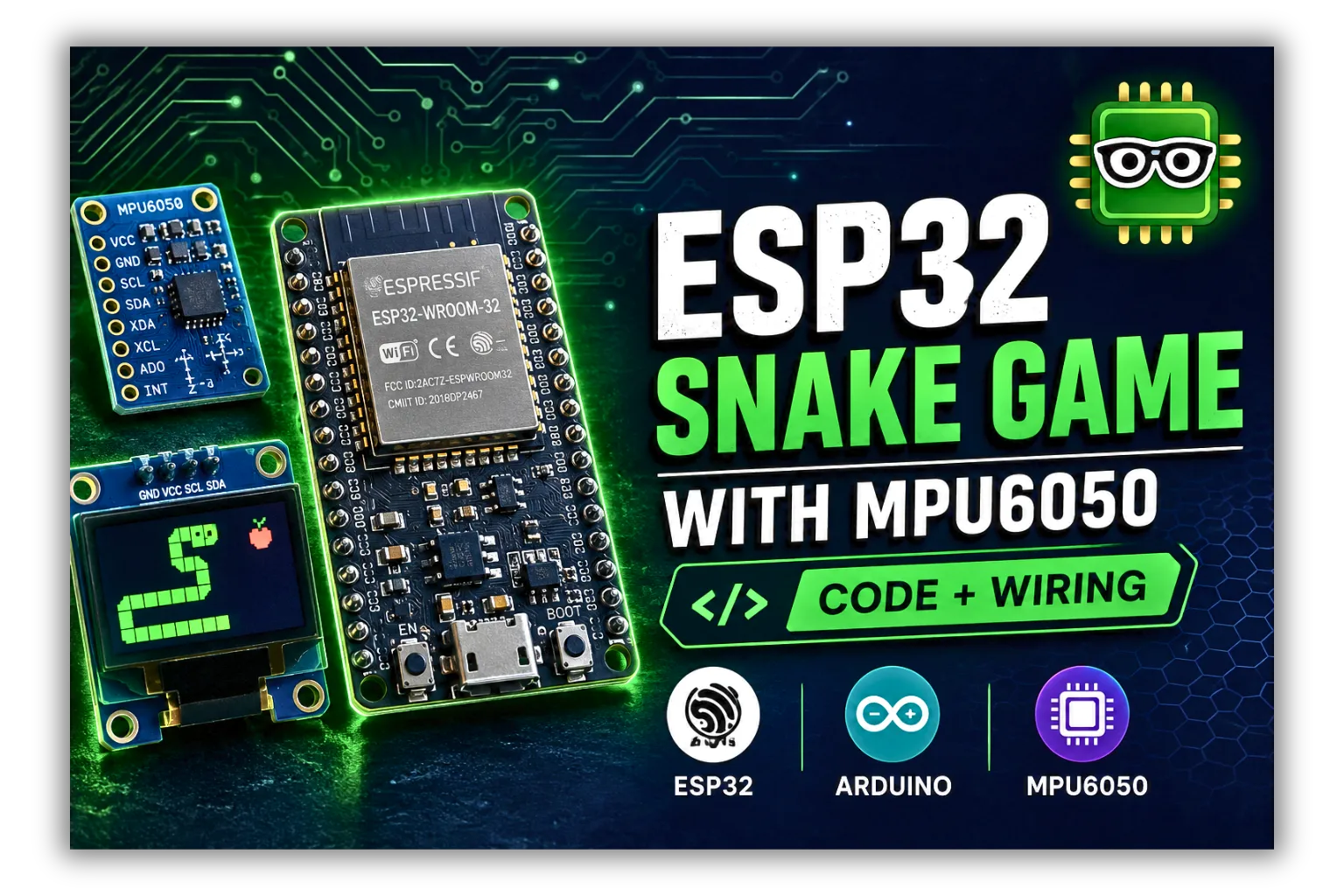
For example, the MPU6050 can be used as a motion controller in the ESP32 Snake Game with MPU6050 and OLED Display.
Important: The calibration values in this example are stored only in RAM. They are lost when the microcontroller is restarted or powered off.
For projects that use the same sensor permanently, the offsets can be saved to non-volatile memory and loaded when the project starts.
Recommended Products
The main hardware for this tutorial is already listed automatically in the Hardware Used in This Project section.
For a new MPU6050 project, the most useful components are:
- MPU6050 accelerometer and gyroscope module
- ESP32 development board
- Solderless breadboard
- Jumper wires
The ESP32 is particularly useful if you want to use the calibrated MPU6050 in a wireless or motion-controlled project.
GitHub Source Code
The complete calibration sketch will be available in the Embedded Nerd GitHub repository.
The repository can be used to download the code and adapt the calibration process to your own MPU6050 projects.
Related Tutorials
If you want to learn more about the MPU6050 and related projects, these guides are a good next step:
- MPU6050 Arduino Guide — Learn how to connect the MPU6050, install the library, and read accelerometer and gyroscope data.
- I2C Scanner Tutorial — Check whether your MPU6050 is detected correctly on the I2C bus.
- ESP32 Snake Game with MPU6050 and OLED Display — Use the MPU6050 as a motion controller in an ESP32 project.
- ESP32 OLED Tutorial — Learn how to connect and use an SSD1306 OLED display with the ESP32.
Future MPU6050 guides can cover topics such as gyroscope drift, troubleshooting, advanced accelerometer calibration, and using the MPU6050 with the ESP32.
Frequently Asked Questions
Does the MPU6050 need calibration?
Calibration is recommended when you need more reliable accelerometer or gyroscope measurements.
The sensor can be used without calibration for simple projects, but reducing its initial offset can improve the results of motion and orientation applications.
How do I calibrate an MPU6050?
Keep the MPU6050 completely stationary, collect multiple accelerometer and gyroscope readings, calculate their average values, and use those measurements to determine the sensor offsets.
The calibration sketch in this guide automates this process.
How do I calibrate the MPU6050 gyroscope?
Keep the sensor completely still while collecting multiple gyroscope samples.
The average X, Y, and Z readings represent the approximate stationary bias and can be used as gyroscope offsets.
After compensation, the stationary gyroscope readings should be close to zero.
How do I calibrate the MPU6050 accelerometer?
For basic offset calibration, place the MPU6050 in a known stationary orientation and measure the accelerometer offsets.
When the sensor is level and configured for ±2g, the expected readings are approximately:
X ≈ 0
Y ≈ 0
Z ≈ 16384
More advanced accelerometer calibration requires measurements in multiple orientations and can compensate for scale and axis errors.
Should the MPU6050 be completely still during calibration?
Yes.
The sensor should remain completely stationary while calibration samples are being collected.
Any movement can be interpreted as sensor bias and result in incorrect calibration values.
Why is my MPU6050 gyroscope not reading zero?
A small non-zero reading from a stationary gyroscope is normal.
If the value is consistently larger, recalibrate the sensor and make sure it remains completely still during the calibration process.
If the readings continue changing significantly over time, the problem may be related to gyroscope drift or environmental conditions.
Why does my MPU6050 accelerometer show 16384?
At the common ±2g accelerometer setting, approximately 16384 raw counts correspond to 1g.
If the MPU6050 is stationary and level, the Z axis should therefore be close to 16384.
The X and Y axes should be closer to zero.
How many samples should I use for MPU6050 calibration?
There is no single required number of samples.
This guide uses 2000 samples as a practical starting point.
Increasing the number of samples can produce a more stable average, but it also increases calibration time.
Does MPU6050 calibration remove gyroscope drift?
No.
Calibration can reduce the initial gyroscope bias, but it does not completely eliminate long-term drift.
Gyroscope drift can also be affected by temperature, noise, sensor characteristics, and integration errors.
A dedicated MPU6050 gyroscope drift guide can cover these issues in more detail.
Do I need to calibrate the MPU6050 every time I turn it on?
Not necessarily.
The calculated offsets can be saved in the microcontroller’s non-volatile memory and loaded when the project starts.
However, recalibration may be useful if the sensor’s operating conditions change significantly.
Can I use this calibration with an ESP32?
Yes.
The MPU6050 communicates with the ESP32 using I2C, and the same basic calibration principle can be used.
The I2C pins and initialization code may differ depending on the ESP32 board.
A dedicated MPU6050 + ESP32 guide can cover the ESP32-specific setup in more detail.
Conclusion
Calibrating an MPU6050 is a simple but important step when you need more reliable motion sensor readings.
By keeping the sensor completely stationary and collecting multiple samples, you can measure its accelerometer and gyroscope offsets and compensate for the sensor’s initial bias.
After calibration:
- The stationary gyroscope should remain close to zero.
- The level accelerometer should produce approximately 0g on X and Y.
- The level accelerometer Z axis should remain close to 1g.
- Small variations caused by sensor noise are normal.
The calibration process described in this guide focuses on practical offset compensation. More advanced applications may require additional accelerometer calibration, temperature compensation, or techniques for dealing with long-term gyroscope drift.
Once the MPU6050 is calibrated, it can be used for motion detection, robotics, orientation tracking, and motion-controlled projects such as the ESP32 Snake Game with MPU6050 and OLED Display.
Share on
X Facebook LinkedIn Bluesky
Hardware Used in This Project

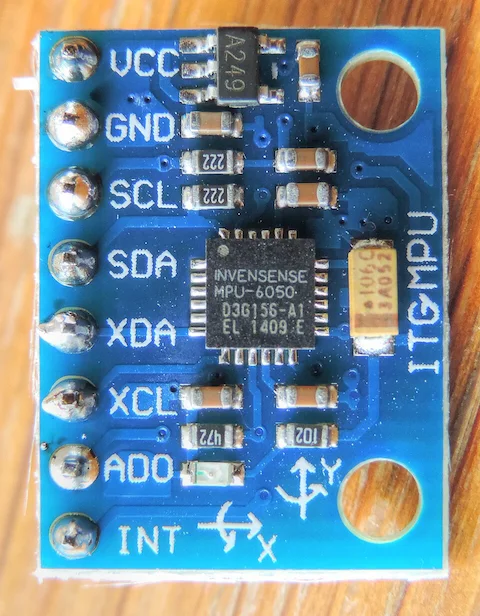
MPU6050 Accelerometer & Gyroscope
MPU6050 6-axis motion sensor combining a 3-axis accelerometer and 3-axis gyroscope with I2C communication.
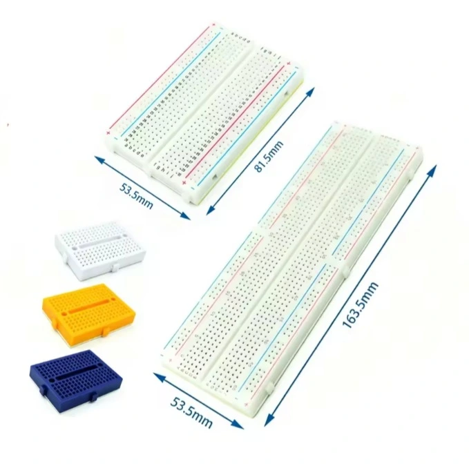
Solderless Breadboard
Reusable solderless breadboard for rapid prototyping of electronic circuits with Arduino, ESP32 and Raspberry Pi.
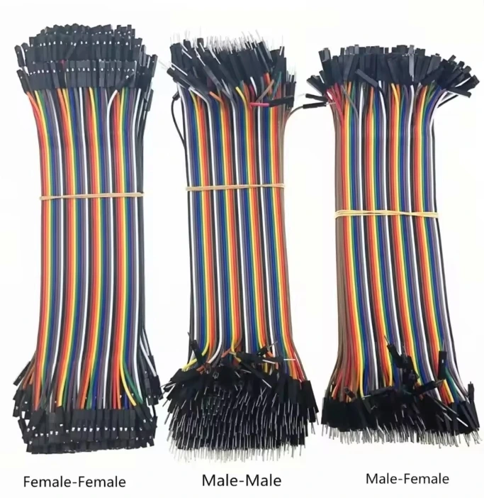
Jumper Wires
Jumper wires for breadboard prototyping with Arduino, ESP32, Raspberry Pi and other embedded development boards.