MPU6050 Arduino Guide: Wiring, Code & I2C
The MPU6050 is a popular motion sensor for Arduino projects because it combines a 3-axis accelerometer and a 3-axis gyroscope in one device.
In this guide, you’ll learn how to connect the MPU6050 to an Arduino Uno or Nano, install a compatible Arduino library, upload working MPU6050 Arduino code and read accelerometer and gyroscope data through I2C.
You’ll also learn how to find the MPU6050 I2C address and troubleshoot the most common connection problems.
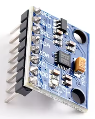
This tutorial covers:
- MPU6050 Arduino wiring
- Arduino Uno and Nano connections
- MPU6050 I2C communication
- MPU6050 I2C address
- MPU6050 Arduino code
- Serial Monitor output
- MPU6050 troubleshooting
- What to do when the MPU6050 is not detected
- Links to the I2C Scanner and calibration guide
What Is the MPU6050?
The MPU6050 is a 6-axis motion-tracking sensor that combines:
- 3-axis accelerometer
- 3-axis gyroscope
- Temperature sensor
- I2C communication
It can be used to measure acceleration, rotation and changes in orientation.
Common MPU6050 Arduino applications include:
- Robotics
- Gesture control
- Motion tracking
- Tilt measurement
- Self-balancing projects
- Motion-controlled games
- Drone and stabilization projects
- DIY electronics
The sensor communicates with a microcontroller using I2C, making it easy to connect to Arduino Uno, Arduino Nano and ESP32 boards.
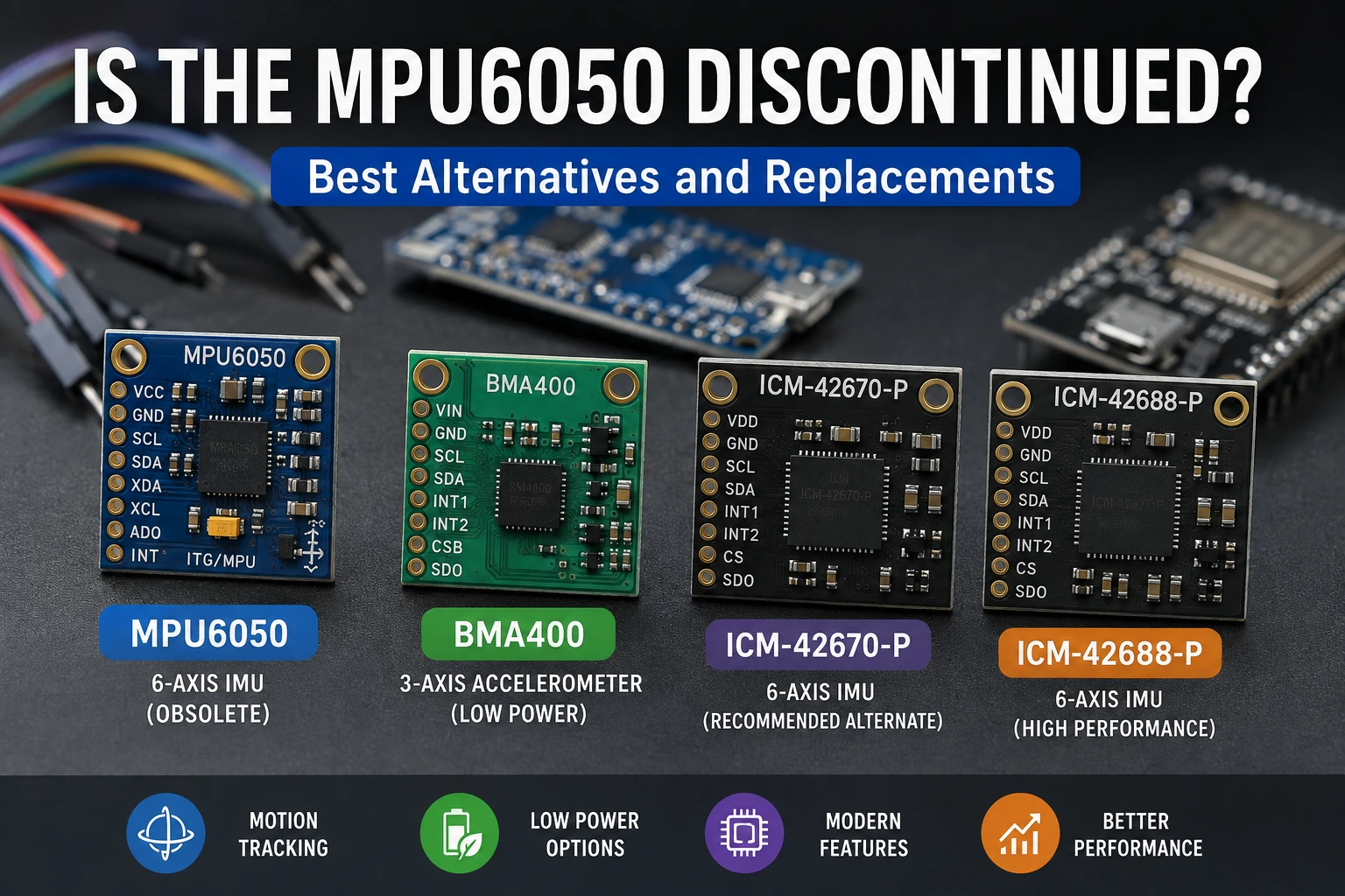
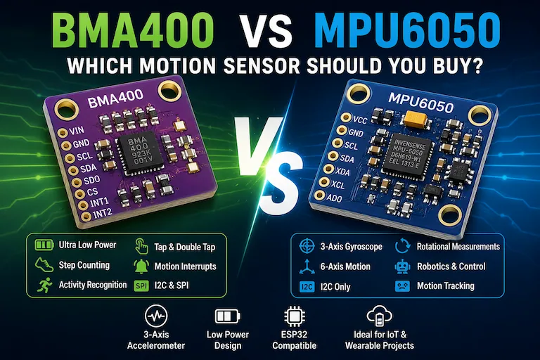
For existing projects and learning, the MPU6050 remains a useful and widely supported sensor. However, if you are starting a new long-term design, it is worth considering newer devices. See our guide to MPU6050 alternatives and replacements, including the BMA400, ICM-42670-P and ICM-42688-P.
The MPU6050 can also show small offsets in its accelerometer and gyroscope readings. For more accurate measurements, see our MPU6050 Calibration Guide.
Required Hardware
| Component | Recommended Product | Buy |
|---|---|---|
| ESP32 Development Board | ESP32 DevKit V1 | 🛒 AliExpress |
| MPU6050 Accelerometer & Gyroscope | MPU6050 Accelerometer & Gyroscope | 🛒 AliExpress |
| Breadboard | Solderless Breadboard | — |
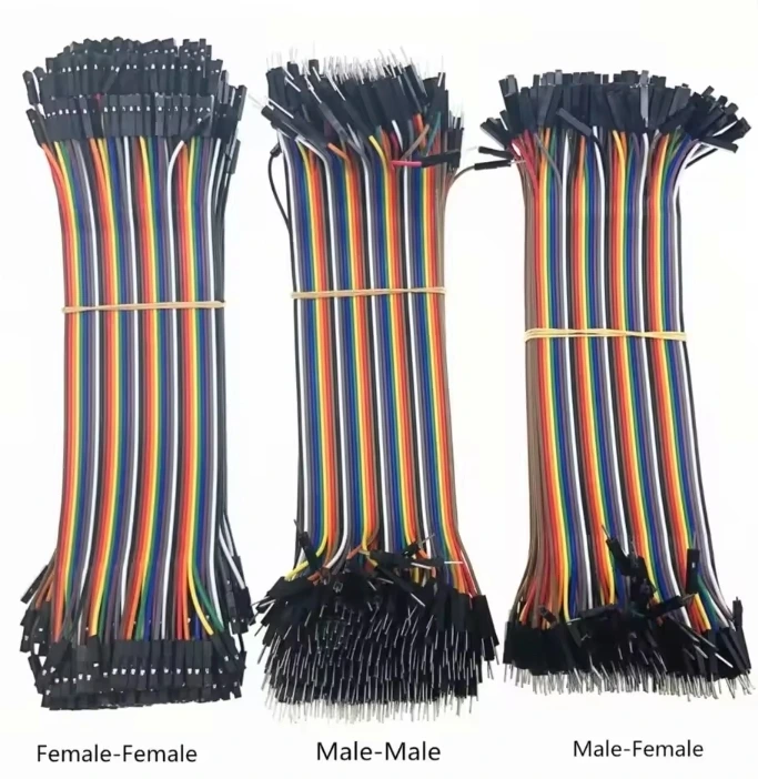
| Male-to-Female Jumper Wires | Jumper Wires | — |
Some links on this page are affiliate links. If you purchase through them, Embedded Nerd may earn a small commission at no additional cost to you. This helps support the website and allows us to continue creating free tutorials and guides. Thank you for your support!
MPU6050 Arduino Wiring
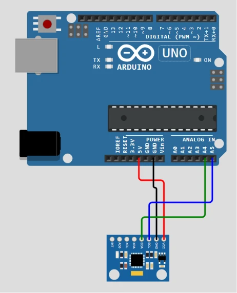
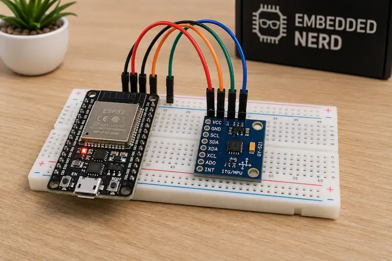
Connecting the MPU6050 to an Arduino Uno is straightforward because the Uno has dedicated I2C pins.
Arduino Uno and Nano Connections
| MPU6050 Pin | Arduino Uno / Nano |
|---|---|
| VCC | Appropriate module supply |
| GND | GND |
| SDA | A4 |
| SCL | A5 |
On the Arduino Uno and Nano:
- A4 → SDA
- A5 → SCL
The correct supply voltage depends on the MPU6050 breakout board you are using.
Important: the MPU6050 sensor itself is a low-voltage device. Some breakout boards include a voltage regulator and level shifting and can accept 5V on VCC, while others do not. Always check the specifications of your particular module before connecting it to 5V.
MPU6050 I2C Address
The MPU6050 normally uses the I2C address:
0x68
The address can also be:
0x69
when the AD0 pin is configured HIGH.
If you’re not sure which address your module is using, run the I2C Scanner Tutorial before troubleshooting the MPU6050 code, or check the I2C Address Lookup Tool for a quick reference.
The scanner can confirm whether the sensor responds on the I2C bus and which address it is using.
Install the MPU6050 Arduino Library
This example uses the MPU6050 library with the Arduino Wire library.
Open Arduino IDE and install a compatible MPU6050 library.
Arduino IDE Steps
- Open Arduino IDE.
- Go to Sketch → Include Library → Manage Libraries.
- Search for MPU6050.
- Install a compatible MPU6050 library.
- Restart Arduino IDE if necessary.
Make sure that the library you install provides the MPU6050.h header and the functions used in the example below.
MPU6050 Arduino Code Example
The following example initializes the MPU6050 and reads accelerometer and gyroscope values.
/*
   Embedded Nerd
   MPU6050 Arduino Example
   https://embeddednerd.com
*/

#include <Wire.h>
#include <MPU6050.h>

MPU6050 mpu;

void setup() {

  Serial.begin(115200);

  Wire.begin();

  mpu.initialize();

  if (mpu.testConnection()) {
    Serial.println("MPU6050 connected successfully");
  } else {
    Serial.println("MPU6050 connection failed");
  }
}

void loop() {

  int16_t ax, ay, az;
  int16_t gx, gy, gz;

  mpu.getMotion6(&ax, &ay, &az, &gx, &gy, &gz);

  Serial.print("Accel X: ");
  Serial.print(ax);

  Serial.print(" | Accel Y: ");
  Serial.print(ay);

  Serial.print(" | Accel Z: ");
  Serial.print(az);

  Serial.print(" | Gyro X: ");
  Serial.print(gx);

  Serial.print(" | Gyro Y: ");
  Serial.print(gy);

  Serial.print(" | Gyro Z: ");
  Serial.println(gz);

  delay(500);
}
How the MPU6050 Arduino Code Works
Wire.begin()
Wire.begin();
This initializes I2C communication.
On an Arduino Uno or Nano, the default I2C pins are A4 for SDA and A5 for SCL.
mpu.initialize()
mpu.initialize();
This initializes the MPU6050 through the library.
mpu.testConnection()
mpu.testConnection();
This checks whether the MPU6050 responds correctly.
If the connection succeeds, the Serial Monitor displays:
MPU6050 connected successfully
If it fails:
MPU6050 connection failed
getMotion6()
mpu.getMotion6(&ax, &ay, &az, &gx, &gy, &gz);
This reads the six motion values:
- Accelerometer X
- Accelerometer Y
- Accelerometer Z
- Gyroscope X
- Gyroscope Y
- Gyroscope Z
The values returned by this example are raw sensor readings. They are not automatically converted to units such as g or degrees per second.
MPU6050 Serial Monitor Output
After uploading the sketch, open the Arduino Serial Monitor and select:
115200 baud
You should see output similar to:
MPU6050 connected successfully
Accel X: -120 | Accel Y: 340 | Accel Z: 16384 | Gyro X: 12 | Gyro Y: -8 | Gyro Z: 3
The exact values will change when you move the sensor.
MPU6050 Arduino Uno and Nano Notes
The MPU6050 works well with:
- Arduino Uno
- Arduino Nano
- ESP32
- Other Arduino-compatible boards
For Arduino Uno and Nano:
A4 → SDA
A5 → SCL
For a typical ESP32:
GPIO21 → SDA
GPIO22 → SCL
The exact pins can vary depending on the board and software configuration.
MPU6050 Not Detected
If the MPU6050 Arduino code reports:
MPU6050 connection failed
check the I2C connection before changing the application code.
Verify:
- VCC is connected correctly.
- GND is connected correctly.
- SDA is connected to SDA.
- SCL is connected to SCL.
- The correct I2C pins are being used.
- The module is receiving the correct voltage.
- The MPU6050 I2C address is correct.
You can use the I2C Scanner Tutorial to check whether the sensor responds on the bus.
MPU6050 I2C Scanner Troubleshooting
If the I2C Scanner does not detect the MPU6050, test one device at a time.
Check for:
- Reversed SDA and SCL wires
- Incorrect power connection
- Loose jumper wires
- Incorrect I2C pins
- Incorrect module voltage
- Wrong I2C address configuration
- Faulty breakout board
The MPU6050 normally appears at 0x68 or 0x69.
If the scanner detects the address but your application still fails, check the library and initialization code.
Random or Unstable MPU6050 Values
Small changes in sensor readings are normal.
Possible causes of unusually unstable readings include:
- Electrical noise
- Poor power supply
- Loose connections
- Sensor movement
- Mechanical vibration
- Uncalibrated sensor
For projects that require more accurate readings, calibration can reduce sensor offsets.
See the MPU6050 Calibration Guide for a complete calibration procedure.
Upload Failed
If the Arduino sketch does not upload, the problem is usually unrelated to the MPU6050.
Check:
- Correct board selected in Arduino IDE
- Correct COM port selected
- USB cable supports data
- No other program is using the serial port
- Arduino is connected correctly
MPU6050 Projects
Once the MPU6050 is working, it can be used for:
- Motion tracking
- Gesture control
- Tilt measurement
- Robotics
- Self-balancing systems
- Motion-controlled games
- Drone stabilization
- OLED motion displays
For example, the MPU6050 can be combined with an OLED display to create a compact motion monitor.
GitHub Source Code
The complete MPU6050 Arduino example can be kept in the Embedded Nerd GitHub repository for reuse in future projects.
The basic example can be expanded with:
- OLED displays
- ESP32 boards
- Motion-controlled games
- Wireless communication
- Sensor calibration
- Data logging
Related Tutorials
If you’re working with the MPU6050 or other I2C devices, these tutorials may also be useful:
- MPU6050 Calibration Guide
- I2C Scanner Tutorial
- ESP32 OLED Tutorial – Wiring, Code & Display Guide
- ESP32 Snake Game
The I2C Scanner is especially useful when the MPU6050 is not detected, while the calibration guide is useful when the sensor is working but the readings need better accuracy.
Frequently Asked Questions
What is the MPU6050 used for?
The MPU6050 is a 6-axis motion sensor that combines a 3-axis accelerometer and 3-axis gyroscope. It can be used for motion tracking, tilt measurement, robotics, gesture control and other Arduino projects.
How do I connect the MPU6050 to Arduino Uno?
Connect:
MPU6050 SDA → Arduino A4
MPU6050 SCL → Arduino A5
MPU6050 GND → Arduino GND
MPU6050 VCC → Appropriate module supply
Check the breakout board specifications before using 5V.
What is the MPU6050 I2C address?
The MPU6050 normally uses 0x68. It can also use 0x69 when the AD0 pin is HIGH.
If you’re unsure, use an I2C Scanner to detect the address.
Why is my MPU6050 not detected?
Check the power supply, SDA and SCL connections, I2C pins and address. Running an I2C Scanner is one of the quickest ways to determine whether the sensor is responding.
Does the MPU6050 work with ESP32?
Yes. The MPU6050 can communicate with an ESP32 using I2C. A typical ESP32 configuration uses GPIO21 for SDA and GPIO22 for SCL.
Does the MPU6050 need calibration?
Calibration is useful when you need more accurate accelerometer and gyroscope measurements because the sensor can have small offsets.
See the MPU6050 Calibration Guide for more information.
Conclusion
The MPU6050 is a versatile motion sensor and an excellent choice for Arduino and ESP32 projects.
With just four main connections, you can connect it to an Arduino Uno or Nano and start reading accelerometer and gyroscope data over I2C.
The most important steps are:
- Connect SDA and SCL correctly.
- Check the module’s power requirements.
- Confirm the MPU6050 I2C address.
- Install a compatible library.
- Upload the Arduino example.
- Use the I2C Scanner if the sensor is not detected.
- Calibrate the sensor when more accurate measurements are required.
Once the basic connection is working, the MPU6050 can be used as the foundation for robotics, motion tracking, gesture control and many other embedded electronics projects.
Share on
X Facebook LinkedIn Bluesky
Hardware Used in This Project
 Recommended
ESP32 DevKit V1
ESP32 DevKit V1 development board with Wi-Fi and Bluetooth. Check specifications, compatibility and current prices for Arduino and IoT projects.
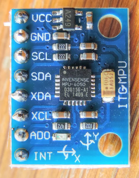
MPU6050 Accelerometer & Gyroscope
MPU6050 6-axis motion sensor combining a 3-axis accelerometer and 3-axis gyroscope with I2C communication.
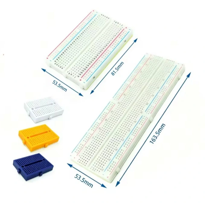
Solderless Breadboard
Reusable solderless breadboard for rapid prototyping of electronic circuits with Arduino, ESP32 and Raspberry Pi.
Jumper Wires
Jumper wires for breadboard prototyping with Arduino, ESP32, Raspberry Pi and other embedded development boards.