ESP32 Joystick Tutorial
Learn how to connect, calibrate, and program an analog joystick module with the ESP32 using the Arduino IDE.
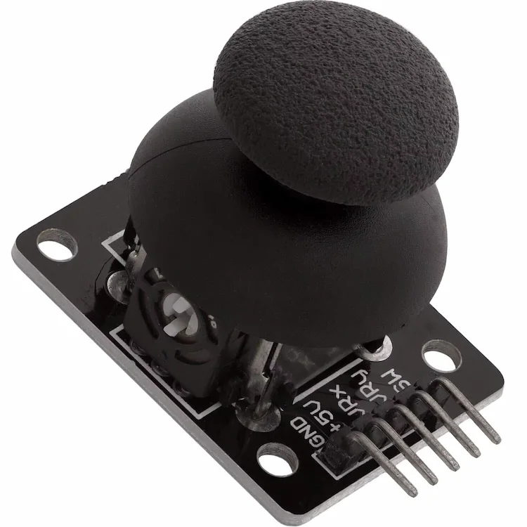
What You’ll Learn
By the end of this tutorial you will be able to:
✔ Understand how an analog joystick works
✔ Connect a KY-023 joystick to any ESP32 board
✔ Read the X and Y analog axes
✔ Detect the built-in push button
✔ Understand how the ESP32 ADC works
✔ Improve accuracy using calibration
✔ Remove unwanted joystick jitter
✔ Create a dead zone
✔ Convert joystick movement into percentages
✔ Control an SG90 servo
✔ Navigate OLED menus
✔ Control robot movement
✔ Build your own joystick-based projects
Why Read This Guide?
The analog joystick is one of the most useful input devices available for embedded systems. Although it looks simple, it can be used in hundreds of projects ranging from small menu navigation systems to autonomous robots.
Unlike digital push buttons, which only detect ON and OFF states, an analog joystick provides proportional movement. This means your ESP32 can determine not only the direction of movement but also how far the joystick has been moved.
That capability opens the door to projects such as:
- Robot control
- Camera pan and tilt systems
- CNC controllers
- RC vehicles
- Drone transmitters
- OLED menu navigation
- Game controllers
- Robotic arms
- Industrial HMIs
- Home automation interfaces
Many beginners simply connect the joystick and call analogRead(). While that works, it rarely produces professional results because analog signals are affected by electrical noise, manufacturing tolerances, and ADC characteristics.
This guide goes much further.
Instead of only showing how to read the joystick, you’ll learn how to build robust applications by calibrating the joystick, filtering noisy readings, implementing a dead zone, and converting analog values into useful engineering units.
Why Use the ESP32?
The ESP32 is one of the most powerful microcontrollers available for hobbyists and professionals.
Compared with traditional Arduino boards, it offers:
| Feature | ESP32 | Arduino UNO |
|---|---|---|
| CPU | Dual-Core 240 MHz | 16 MHz |
| ADC Resolution | 12-bit | 10-bit |
| ADC Values | 0–4095 | 0–1023 |
| Wi-Fi | ✔ | ✘ |
| Bluetooth | ✔ | ✘ |
| RAM | 520 KB | 2 KB |
| PWM Channels | 16 | 6 |
| Price | Low | Low |
For joystick-based projects, the higher ADC resolution makes a significant difference because movements become smoother and more precise.
What Is an Analog Joystick?
An analog joystick is essentially two potentiometers mounted at 90 degrees from each other.
One potentiometer measures horizontal movement (X-axis).
The second measures vertical movement (Y-axis).
A small mechanical switch located underneath the stick detects when the joystick is pressed downward.
Internally, each potentiometer behaves like a voltage divider.
When the joystick moves, the output voltage changes continuously between ground and the supply voltage.
The ESP32 converts that voltage into a digital value using its built-in Analog-to-Digital Converter (ADC).
For a 12-bit ADC, that value ranges from:
| Voltage | ADC Reading |
|---|---|
| 0 V | 0 |
| 1.65 V | ≈2048 |
| 3.3 V | 4095 |
Because the joystick produces continuous values instead of simple HIGH or LOW signals, it allows smooth proportional control.
For example:
- Push slightly forward → Robot moves slowly
- Push fully forward → Robot moves at maximum speed
- Move halfway left → Servo rotates halfway
- Return to center → Robot stops
This proportional control is what makes analog joysticks far more versatile than directional buttons.
Typical Applications
The KY-023 joystick module is commonly found in projects such as:
- Mobile robots
- Robot arms
- RC vehicles
- Drone controllers
- Camera stabilizers
- CNC machine controllers
- OLED menu navigation
- Smart home interfaces
- Electronic games
- Industrial operator panels
- Educational robotics
- DIY game consoles
If you have ever used a PlayStation, Xbox, or Nintendo controller, you have already used the same basic principle explained in this tutorial.
How Does the KY-023 Work?
The KY-023 module combines three independent devices on a single board:
- X-axis potentiometer
- Y-axis potentiometer
- Push button
Each potentiometer has approximately 10 kΩ of resistance.
When the joystick moves, the resistance changes, creating a different output voltage that the ESP32 measures using its ADC.
The push button is completely independent of the analog outputs.
It simply connects the SW pin to GND whenever the joystick is pressed downward.
Using the ESP32’s internal pull-up resistor, reading the button becomes extremely simple:
- HIGH → Not pressed
- LOW → Pressed
No external resistor is required.
Tip
Although the module is often labeled +5V, it is strongly recommended to power it from 3.3V when using an ESP32. This ensures the analog outputs never exceed the ESP32’s maximum input voltage.
Hardware Overview
Before connecting the joystick, it’s worth taking a few minutes to understand how the hardware works. Knowing what each pin does and why specific GPIOs are chosen will help you avoid unstable readings, Wi-Fi conflicts, and damaged inputs.
In this section you’ll learn:
- The joystick pinout
- The ESP32 ADC architecture
- Why ADC1 is preferred
- GPIOs to avoid
- Recommended wiring
- Power supply recommendations
Hardware Required
| Component | Quantity | Notes | Amazon |
|---|---|---|---|
| ESP32 Development Board | 1 | ESP32-WROOM-32 or equivalent | Affiliate Link |
| KY-023 Analog Joystick Module | 1 | 5-pin module | Affiliate Link |
| Breadboard | 1 | Half or full size | Affiliate Link |
| Jumper Wires | 5 | Male-Male | Affiliate Link |
| USB Cable | 1 | Data cable | Affiliate Link |
Joystick Module Pinout
The KY-023 joystick module exposes five pins.
| Pin | Function |
|---|---|
| GND | Ground |
| +5V | Power Supply |
| VRx | Analog X-axis Output |
| VRy | Analog Y-axis Output |
| SW | Push Button Output |
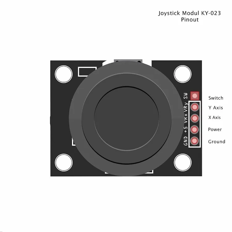
Although many modules print +5V, the joystick works perfectly from 3.3V.
Powering it from 3.3V is actually recommended because the ESP32 ADC inputs are not 5V tolerant.
Warning
Never connect analog outputs exceeding 3.3V directly to ESP32 GPIOs.
Understanding Each Pin
GND
Ground is the common voltage reference shared between the ESP32 and the joystick.
Without a common ground, the analog readings become unpredictable.
Always connect:
Joystick GND
      │
      ▼
ESP32 GND
VCC
This powers both potentiometers.
Recommended:
ESP32 3V3
      │
      ▼
Joystick VCC
Although the board usually says +5V, the internal potentiometers operate perfectly at 3.3V.
VRx
Outputs an analog voltage representing horizontal movement.
Typical values:
| Position | Voltage | ADC Reading |
|---|---|---|
| Left | 0V | ~0 |
| Center | 1.65V | ~2048 |
| Right | 3.3V | ~4095 |
VRy
Exactly the same concept applies to the vertical axis.
| Position | Voltage | ADC Reading |
|---|---|---|
| Down | 0V | ~0 |
| Center | 1.65V | ~2048 |
| Up | 3.3V | ~4095 |
SW
The push button is completely independent.
It behaves like a normal switch.
When pressed:
SW
 │
 ▼
GND
Using INPUT_PULLUP:
| Button | Reading |
|---|---|
| Released | HIGH |
| Pressed | LOW |
No external resistor is required.
Understanding the ESP32 ADC
This is one of the biggest differences between an ESP32 and a traditional Arduino.
The ESP32 contains two independent Analog-to-Digital Converters:
- ADC1
- ADC2
Although both can read analog voltages, they behave differently.
ADC Resolution
The ADC converts an analog voltage into a digital number.
For the default 12-bit resolution:
| Voltage | Digital Reading |
|---|---|
| 0V | 0 |
| 0.825V | ~1024 |
| 1.65V | ~2048 |
| 2.475V | ~3072 |
| 3.3V | 4095 |
This gives the ESP32 four times the precision of an Arduino UNO.
| Board | ADC Bits | Values |
|---|---|---|
| Arduino UNO | 10 | 1024 |
| ESP32 | 12 | 4096 |
The higher resolution allows much smoother joystick movement.
ADC1 vs ADC2
This topic confuses many beginners.
The ESP32 contains two ADC peripherals.
ADC1
GPIO32
GPIO33
GPIO34
GPIO35
GPIO36
GPIO39
✅ Safe to use with Wi-Fi
ADC2
GPIO0
GPIO2
GPIO4
GPIO12
GPIO13
GPIO14
GPIO15
GPIO25
GPIO26
GPIO27
⚠ These pins stop providing reliable analog readings whenever Wi-Fi is active.
Since most ESP32 projects eventually use Wi-Fi or Bluetooth, it is good practice to always use ADC1 whenever possible.
That is why this tutorial uses:
- GPIO34
- GPIO35
Tip
Even if your current project doesn’t use Wi-Fi, choosing ADC1 makes your code future-proof.
Choosing the GPIOs
Our wiring will be:
| Joystick | ESP32 |
|---|---|
| GND | GND |
| VCC | 3V3 |
| VRx | GPIO34 |
| VRy | GPIO35 |
| SW | GPIO32 |
These pins provide:
✔ Stable ADC readings
✔ No Wi-Fi conflicts
✔ Clean layout
✔ Easy expansion
Wiring Diagram
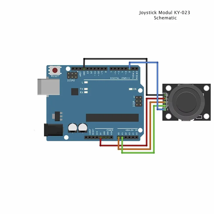
Follow the connections exactly as shown.
Double-check every wire before powering the ESP32.
Most joystick problems are simply caused by swapped VCC and GND connections.
Power Supply Considerations
The joystick itself consumes very little current.
Typical current consumption:
| Device | Current |
|---|---|
| KY-023 | <5 mA |
This makes it perfectly safe to power directly from the ESP32’s 3.3V regulator.
No external power supply is required.
Analog Noise
One thing beginners often notice is that the joystick values are never perfectly stable.
Instead of reading:
2048
2048
2048
2048
you may observe:
2043
2049
2052
2046
2048
This is completely normal.
Small variations are caused by:
- ADC quantization
- Electrical noise
- Potentiometer tolerances
- Breadboard contact resistance
Later in this tutorial we’ll eliminate most of this noise using software filtering and a dead zone.
Note
Small variations of ±10 to ±30 ADC counts are completely normal and do not indicate a faulty joystick.
Before Continuing
At this point you should have:
✅ ESP32 connected
✅ Joystick wired
✅ Correct GPIOs selected
✅ Powered from 3.3V
✅ Common ground connected
In the next section we’ll configure the Arduino IDE, upload the first sketch, and verify that the joystick is working correctly before building more advanced projects.
In the next section we’ll examine every pin of the joystick module, understand what each one does, and see why choosing the correct ESP32 GPIOs is important for reliable analog readings.
Reading the Joystick with the ESP32
Now that the hardware is connected correctly, it’s time to write our first program.
Our initial goal is simple:
- Read the X-axis
- Read the Y-axis
- Read the push button
- Display everything on the Serial Monitor
Although this sounds straightforward, there are a few ESP32-specific details worth understanding before writing any code.
By the end of this section, you’ll have a reliable test program that can serve as the foundation for every joystick-based project.
Preparing the Arduino IDE
If you have already installed ESP32 support in the Arduino IDE, you can skip this section.
Otherwise:
- Open Arduino IDE
- Go to File → Preferences
- Add the ESP32 Boards Manager URL:
https://raw.githubusercontent.com/espressif/arduino-esp32/gh-pages/package_esp32_index.json
- Open:
Tools
    ↓
Board
    ↓
Boards Manager
- Search for:
esp32
- Install the package published by Espressif Systems.
After installation, select your board.
For most users:
Tools
    ↓
Board
    ↓
ESP32 Dev Module
If you own another ESP32 variant, choose the appropriate board.
Understanding the ADC Resolution
The ESP32 converts voltages into numbers.
By default, the ADC uses 12-bit resolution.
That means:
| Voltage | Reading |
|---|---|
| 0V | 0 |
| 3.3V | 4095 |
This gives:
4096 possible values
instead of only
1024 values
available on an Arduino UNO.
The higher resolution produces smoother joystick movement.
ADC Attenuation
One feature many ESP32 tutorials ignore is ADC attenuation.
Attenuation changes the voltage range that the ADC can measure.
For joystick applications powered from 3.3V, the recommended setting is:
analogSetPinAttenuation(xAxisPin, ADC_11db);
analogSetPinAttenuation(yAxisPin, ADC_11db);
Why?
Because it allows the ADC to measure almost the full voltage range generated by the joystick.
Without proper attenuation, the ADC may saturate earlier than expected depending on the ESP32 model.
Tip
Most ESP32 development boards work well without explicitly setting attenuation, but configuring it makes your code more portable across different ESP32 variants.
The First Test Program
Upload the following sketch.
/*
    Embedded Nerd
    ESP32 Analog Joystick Test
*/

const byte xAxisPin = 34;
const byte yAxisPin = 35;
const byte buttonPin = 32;

void setup()
{
    Serial.begin(115200);

    pinMode(buttonPin, INPUT_PULLUP);

    analogSetPinAttenuation(xAxisPin, ADC_11db);
    analogSetPinAttenuation(yAxisPin, ADC_11db);

    Serial.println();
    Serial.println("ESP32 Analog Joystick Test");
    Serial.println("--------------------------");
}

void loop()
{
    int xValue = analogRead(xAxisPin);

    int yValue = analogRead(yAxisPin);

    bool buttonPressed =
        digitalRead(buttonPin) == LOW;

    Serial.print("X: ");
    Serial.print(xValue);

    Serial.print("    Y: ");
    Serial.print(yValue);

    Serial.print("    Button: ");

    if(buttonPressed)
        Serial.println("Pressed");
    else
        Serial.println("Released");

    delay(100);
}
Upload the sketch and open the Serial Monitor.
Set the baud rate to:
115200 baud
Expected Output
With the joystick untouched, you should observe something similar to:
X: 2048    Y: 2055    Button: Released

X: 2052    Y: 2044    Button: Released

X: 2046    Y: 2050    Button: Released
Do not worry if your values are slightly different.
Every joystick has small manufacturing tolerances.
Typical center values are anywhere between:
1980

and

2120
This is perfectly normal.
Moving the Joystick
Try moving the joystick slowly.
You should notice:
Moving left:
X decreases
Moving right:
X increases
Moving down:
Y decreases
Moving up:
Y increases
At the extremes, values should approach:
0

and

4095
although they rarely reach these exact numbers.
Testing the Push Button
Press the joystick downward.
The Serial Monitor should display:
Button: Pressed
Release it.
The message changes back to:
Button: Released
No external resistor is required because we enabled the ESP32’s internal pull-up resistor.
Why Aren’t the Center Values Exactly 2048?
Many beginners expect:
2048
2048
2048
every time.
Real joysticks don’t work like that.
Several factors affect the reading:
- Potentiometer tolerance
- ADC offset
- Temperature
- Electrical noise
- USB power quality
Seeing values such as:
2036

2051

2044

2060
is completely normal.
Professional projects always compensate for these variations using calibration.
We’ll implement that later.
Monitoring the Analog Signal
Spend a minute moving the joystick in every direction.
Observe how smoothly the values change.
Notice that:
Small movement
↓
Small change
Large movement
↓
Large change
This proportional behaviour is exactly what makes analog joysticks so useful.
Unlike digital buttons, they provide continuous position information instead of only ON and OFF states.
Common Beginner Mistakes
Values Stay at Zero
Possible causes:
- Missing power
- Broken wire
- Wrong GPIO
- Poor breadboard connection
Values Stay Near 4095
Usually indicates:
- VCC and GND swapped
- Short circuit
- Wrong wiring
Button Never Changes
Verify:
pinMode(buttonPin, INPUT_PULLUP);
If omitted, the button input will float and produce random readings.
Random Numbers
Random values usually indicate:
- Loose jumper wires
- Missing GND connection
- Faulty breadboard
Always verify the wiring before changing the software.
Note
If your readings vary by ±20 counts while the joystick is stationary, don’t worry. This is completely normal and will be corrected in the next section using software filtering.
What’s Next?
At this point your joystick is working correctly.
However, the readings still aren’t suitable for professional applications.
The next section will dramatically improve their quality by implementing:
- Automatic joystick calibration
- Center detection
- Dead zone
- Moving Average filtering
- Noise reduction
- Stable analog readings
These techniques are used in game controllers, robotics, drones, CNC machines, and industrial control systems, and they will make your projects feel much smoother and more responsive.
Calibrating the Joystick and Eliminating Noise
If you’ve watched the Serial Monitor while the joystick is at rest, you’ve probably noticed that the values are never perfectly stable.
Instead of always reading:
X = 2048
Y = 2048
you’ll typically see something like:
2045
2048
2052
2047
2044
2050
This behavior is completely normal.
It does not mean that your joystick is faulty.
Professional game controllers, drone transmitters, RC radios, and industrial joysticks all experience small variations in their analog signals. The difference is that they process those signals before using them.
In this section, you’ll learn the same techniques used in professional systems:
- Automatic center calibration
- Dead zone implementation
- Moving average filtering
- Value normalization
- Direction detection
Once these techniques are applied, the joystick will feel significantly smoother and more accurate.
Why Analog Signals Are Noisy
An analog joystick is built around two mechanical potentiometers.
Unlike digital components, potentiometers are never perfectly stable.
Several factors contribute to small fluctuations:
- Mechanical tolerances
- ADC conversion error
- Electrical noise
- USB power ripple
- Breadboard contact resistance
- Temperature changes
Because of this, it is unrealistic to expect the center position to always produce exactly the same value.
Even expensive industrial joysticks exhibit some degree of analog noise.
Automatic Center Calibration
Every joystick is slightly different.
One joystick may rest at:
X = 2034
Y = 2058
Another might rest at:
X = 2086
Y = 2012
For this reason, professional software never assumes that the center is exactly 2048.
Instead, it measures the center automatically during startup.
Calibration Code
int centerX;
int centerY;

void calibrateJoystick()
{
    long sumX = 0;
    long sumY = 0;

    const int samples = 100;

    Serial.println("Calibrating joystick...");

    for(int i = 0; i < samples; i++)
    {
        sumX += analogRead(xAxisPin);
        sumY += analogRead(yAxisPin);

        delay(5);
    }

    centerX = sumX / samples;
    centerY = sumY / samples;

    Serial.print("Center X: ");
    Serial.println(centerX);

    Serial.print("Center Y: ");
    Serial.println(centerY);
}
Call the function once inside setup() after initializing the Serial port.
calibrateJoystick();
The joystick should remain untouched during calibration.
Tip
Averaging many samples produces a much more accurate center value than taking a single reading.
Creating a Dead Zone
Even after calibration, the joystick may continue producing tiny movements while resting.
Imagine the center value is:
2048
The ADC may still report:
2045

2051

2047

2053
Although these changes are insignificant, your software might interpret them as real movement.
A dead zone solves this problem.
Any movement smaller than a predefined threshold is ignored.
Dead Zone Example
const int deadZone = 40;

int x = analogRead(xAxisPin);

if(abs(x - centerX) < deadZone)
{
    x = centerX;
}
The same logic should be applied to the Y axis.
Why Use a Dead Zone?
Without one, a robot may slowly drift across the floor, a servo may continuously vibrate, or a cursor on an OLED display may move on its own.
A dead zone ensures that small fluctuations around the center are treated as intentional “no movement.”
Choosing the Right Dead Zone
| Dead Zone | Feel |
|---|---|
| 10 | Very sensitive |
| 20 | Sensitive |
| 40 | Recommended |
| 60 | Smooth |
| 100 | Less responsive |
For most projects, a value between 30 and 50 ADC counts works very well.
Moving Average Filter
Another way to reduce noise is by averaging multiple consecutive readings.
Instead of using:
analogRead()
once,
we calculate the average of several measurements.
Moving Average Function
int readAverage(int pin)
{
    long total = 0;

    const int samples = 10;

    for(int i = 0; i < samples; i++)
    {
        total += analogRead(pin);
    }

    return total / samples;
}
Now read the joystick like this:
int x = readAverage(xAxisPin);
int y = readAverage(yAxisPin);
The movement becomes noticeably smoother.
Advantages
✔ Reduced electrical noise
✔ More stable readings
✔ Better servo movement
✔ Better robot control
✔ More professional feel
Disadvantages
A larger average also makes the joystick slightly slower to respond.
Typical values are:
| Samples | Response |
|---|---|
| 4 | Fast |
| 8 | Recommended |
| 10 | Smooth |
| 20 | Very smooth |
| 50 | Slow |
Eight to ten samples provide an excellent balance between smoothness and responsiveness.
Normalizing the Values
Once the joystick is calibrated, it is useful to convert the readings into values relative to the center.
Instead of working with:
2035

2052

1988
we subtract the center value.
int normalizedX =
    analogRead(xAxisPin) - centerX;

int normalizedY =
    analogRead(yAxisPin) - centerY;
Now the center becomes:
0
Moving left produces negative values.
Moving right produces positive values.
For example:
| Position | Value |
|---|---|
| Full Left | -2048 |
| Center | 0 |
| Full Right | +2047 |
This representation is much easier to use in robotics and control systems.
Detecting Direction
Using the normalized values, detecting movement direction becomes straightforward.
if(normalizedX > 300)
{
    Serial.println("RIGHT");
}

else if(normalizedX < -300)
{
    Serial.println("LEFT");
}

if(normalizedY > 300)
{
    Serial.println("UP");
}

else if(normalizedY < -300)
{
    Serial.println("DOWN");
}
Diagonal movements can also be detected by combining both axes.
For example:
UP + RIGHT

↓

UP-RIGHT
This technique is widely used in games and robotic navigation.
Combining Everything
A professional joystick reading typically follows this sequence:
- Read the ADC
- Average multiple samples
- Apply calibration
- Normalize the values
- Apply the dead zone
- Detect the direction
- Use the processed values in the application
This processing pipeline produces smooth, accurate, and repeatable results.
Best Practice
Avoid using raw
analogRead()values directly in real projects. Applying calibration, filtering, and a dead zone significantly improves the user experience with very little additional code.
What’s Next?
Your joystick is now producing clean and reliable data.
In the next section, we’ll use these processed values to control real hardware.
We’ll start by driving an SG90 servo motor smoothly, then expand the project to control DC motors, navigate OLED menus, and build more advanced applications.
Mini Project: Smooth Servo Control with the ESP32 Joystick
Now that we have clean, calibrated joystick readings, it’s time to control a real actuator.
In this project, the joystick’s X-axis will control the position of an SG90 micro servo.
Unlike many basic tutorials, we won’t simply map the joystick directly to the servo angle. Instead, we’ll implement:
- Smooth movement
- Dead zone support
- Servo speed limiting
- Stable operation
- Proper power recommendations
These improvements produce much more natural movement and prevent the servo from constantly vibrating around its center position.
Hardware Required
| Component | Quantity |
|---|---|
| ESP32 Dev Board | 1 |
| KY-023 Joystick | 1 |
| SG90 Servo | 1 |
| Breadboard | 1 |
| Jumper Wires | Several |
Servo Wiring
| SG90 Wire | ESP32 |
|---|---|
| Brown | GND |
| Red | External 5V* |
| Orange | GPIO18 |
*An external 5V power supply is strongly recommended.
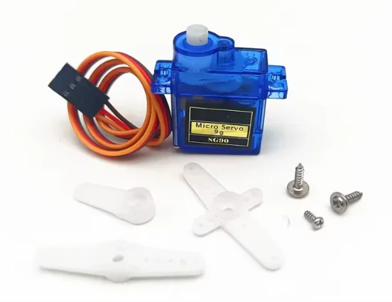
Warning
Never power multiple servos directly from the ESP32’s 3.3V pin. Even a small SG90 can draw over 500 mA during startup or when stalled. An overloaded power supply may cause random ESP32 resets or unstable operation.
Why Use an External Power Supply?
Many beginners connect the servo directly to the ESP32.
Although this may work for quick tests, it often causes problems.
An SG90 typically consumes:
| Condition | Current |
|---|---|
| Idle | 10–20 mA |
| Moving | 150–250 mA |
| Stall | Up to 650 mA |
The ESP32 cannot safely provide this current under all conditions.
The recommended wiring is:
External 5V
      │
      ├──── Servo VCC

ESP32 GND
      │
      ├──── Servo GND
      └──── Power Supply GND
The grounds must be connected together.
Without a common ground, the PWM control signal will not have a proper voltage reference.
Installing the Servo Library
The standard Arduino Servo library is not fully compatible with the ESP32.
Instead, install:
ESP32Servo
by Kevin Harrington.
Open:
Sketch

↓

Include Library

↓

Manage Libraries
Search for:
ESP32Servo
Install the latest version.
Complete Project Code
#include <ESP32Servo.h>

const byte xAxisPin = 34;
const byte servoPin = 18;

Servo myServo;

int centerX;
int currentAngle = 90;

const int deadZone = 40;

void calibrateJoystick()
{
    long sum = 0;

    for(int i = 0; i < 100; i++)
    {
        sum += analogRead(xAxisPin);
        delay(5);
    }

    centerX = sum / 100;
}

void setup()
{
    Serial.begin(115200);

    analogSetPinAttenuation(xAxisPin, ADC_11db);

    calibrateJoystick();

    ESP32PWM::allocateTimer(0);

    myServo.setPeriodHertz(50);

    myServo.attach(servoPin,500,2400);

    myServo.write(currentAngle);
}

void loop()
{
    int x = analogRead(xAxisPin);

    if(abs(x-centerX)<deadZone)
        x=centerX;

    int targetAngle=
        map(x,0,4095,0,180);

    if(targetAngle>currentAngle)
        currentAngle++;

    if(targetAngle<currentAngle)
        currentAngle--;

    myServo.write(currentAngle);

    delay(10);
}
How the Code Works
The program begins by calibrating the joystick.
Instead of assuming the center is exactly 2048, it measures the actual center value during startup.
After calibration, each loop performs the following sequence:
- Read the joystick.
- Apply the dead zone.
- Convert the ADC value into an angle.
- Move the servo smoothly toward the target.
- Repeat.
Instead of instantly jumping to the new position, the servo moves one degree at a time.
This creates much smoother movement.
Why Smooth Movement Matters
Many beginner examples use:
servo.write(map(analogRead(...)));
Although simple, this produces abrupt movement.
Even tiny ADC fluctuations cause constant servo corrections.
The result is:
- Jitter
- Noise
- Excessive wear
- Higher current consumption
By gradually moving toward the target position, the servo behaves much more naturally.
Understanding the map() Function
The joystick produces values between:
0

↓

4095
The servo expects:
0°

↓

180°
The map() function converts one range into another.
int angle =
map(x,0,4095,0,180);
Examples:
| ADC | Servo Angle |
|---|---|
| 0 | 0° |
| 1024 | 45° |
| 2048 | 90° |
| 3072 | 135° |
| 4095 | 180° |
Limiting the Servo Range
Some mechanical systems should not rotate through the full 180°.
You can limit the travel easily.
Instead of:
map(x,0,4095,0,180);
use:
map(x,0,4095,20,160);
This protects gears and mechanical linkages.
Adjusting the Servo Speed
The movement speed depends on this section:
currentAngle++;
or
currentAngle--;
Increasing by one degree per loop creates smooth motion.
Increasing by:
currentAngle+=3;
makes the servo respond faster.
Experiment to find the best balance for your application.
Returning to the Center
Because we implemented a dead zone, releasing the joystick causes the servo to return smoothly to approximately 90°.
This behaviour is ideal for:
- Camera pan systems
- Robot steering
- Turret control
- RC transmitters
Troubleshooting
Servo Doesn’t Move
Check:
- External power supply
- Common ground
- Correct GPIO
- ESP32Servo installed
Servo Vibrates
Possible causes:
- No dead zone
- Poor power supply
- Loose wiring
ESP32 Keeps Resetting
Almost always caused by powering the servo from the ESP32.
Use an external 5V supply.
Servo Only Moves Partially
Verify:
myServo.attach(servoPin,500,2400);
Different servos require slightly different pulse widths.
Ideas for Further Improvements
Now that the servo is working reliably, you can extend the project in several ways.
- Use the Y-axis to control a second servo and build a pan-tilt camera platform.
- Press the joystick button to store preset positions.
- Add acceleration and deceleration for even smoother movement.
- Display the current angle on an OLED screen.
- Send joystick commands wirelessly over Wi-Fi or Bluetooth.
- Control a robotic arm with multiple joints.
These ideas all build upon the same concepts you’ve learned in this chapter.
What’s Next?
Controlling a servo is an excellent introduction, but many real projects require controlling motors rather than position.
In the next chapter, you’ll learn how to use the joystick to drive a DC motor through an H-bridge driver, enabling proportional speed and direction control. The same principles can then be applied to mobile robots, RC vehicles, conveyor systems, and other motion-control applications.
Mini Project: Controlling a DC Motor with the ESP32 Joystick
So far we’ve learned how to read the joystick accurately and use it to control a servo motor.
The next logical step is controlling DC motors.
This is where analog joysticks truly shine.
Unlike push buttons, which can only turn a motor fully ON or OFF, an analog joystick lets you control both speed and direction proportionally.
Push the joystick slightly forward and the motor rotates slowly.
Push it fully forward and it reaches maximum speed.
This behaviour is exactly how radio-controlled cars, mobile robots, forklifts, wheelchairs, and industrial vehicles are controlled.
Why You Need a Motor Driver
One of the most common beginner mistakes is attempting to connect a DC motor directly to an ESP32 GPIO.
This will not work.
An ESP32 GPIO can only supply a small amount of current, while even a tiny DC motor may require hundreds of milliamps when starting.
A motor driver acts as an interface between the ESP32 and the motor.
It provides:
- Higher current capability
- Direction control
- Speed control through PWM
- Protection for the ESP32
Popular motor drivers include:
| Driver | Voltage | Efficiency | Recommendation |
|---|---|---|---|
| L298N | 5–35 V | Medium | Beginner |
| TB6612FNG | 4.5–13.5 V | High | Recommended |
| DRV8833 | 2.7–10.8 V | High | Small robots |
| BTS7960 | Up to 43 A | Very High | Large motors |
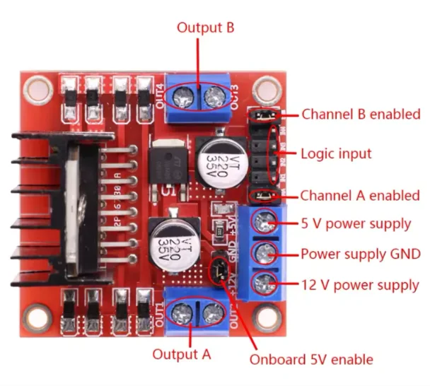
For this tutorial we’ll use the widely available L298N.
Hardware Required
| Component | Quantity |
|---|---|
| ESP32 Dev Board | 1 |
| KY-023 Joystick | 1 |
| L298N Motor Driver | 1 |
| DC Motor | 1 |
| External Motor Supply | 1 |
| Breadboard and Jumper Wires | Several |
Wiring Diagram
| L298N | ESP32 |
|---|---|
| ENA | GPIO25 |
| IN1 | GPIO26 |
| IN2 | GPIO27 |
| GND | GND |
Motor power:
Battery +

↓

L298N +12V

Battery -

↓

L298N GND
ESP32 GND must be connected to the L298N GND.
Important
The motor should always be powered from an external battery or power supply. Never attempt to power a DC motor directly from the ESP32.
How the Control Works
We’ll use the joystick’s Y-axis.
The joystick center represents:
Motor Stopped
Moving forward:
Forward

↓

Increasing Speed
Moving backward:
Reverse

↓

Increasing Speed
The further the joystick moves from the center, the faster the motor rotates.
Reading the Y-Axis
Assuming the joystick has already been calibrated:
int y = analogRead(yAxisPin);

y -= centerY;
Now the values become approximately:
| Position | Reading |
|---|---|
| Full Reverse | -2048 |
| Center | 0 |
| Full Forward | +2047 |
This representation is much easier to work with.
Applying a Dead Zone
To prevent the motor from creeping when the joystick is released:
if(abs(y) < 40)
{
    y = 0;
}
Now the motor stops completely around the center position.
Converting the Reading into PWM
The ESP32 PWM range is:
0

↓

255
We therefore convert the joystick value into PWM.
int pwm =
map(abs(y),0,2048,0,255);
Examples:
| Joystick | PWM |
|---|---|
| Center | 0 |
| 25% | 64 |
| 50% | 128 |
| 75% | 192 |
| Full | 255 |
This produces smooth speed control.
Controlling Direction
Forward:
digitalWrite(IN1,HIGH);
digitalWrite(IN2,LOW);
Reverse:
digitalWrite(IN1,LOW);
digitalWrite(IN2,HIGH);
Stop:
digitalWrite(IN1,LOW);
digitalWrite(IN2,LOW);
Simple and reliable.
Complete Example
int y = analogRead(yAxisPin);

y -= centerY;

if(abs(y) < 40)
{
    y = 0;
}

int pwm =
map(abs(y),0,2048,0,255);

if(y > 0)
{
    digitalWrite(IN1,HIGH);
    digitalWrite(IN2,LOW);

    ledcWrite(0,pwm);
}
else if(y < 0)
{
    digitalWrite(IN1,LOW);
    digitalWrite(IN2,HIGH);

    ledcWrite(0,pwm);
}
else
{
    digitalWrite(IN1,LOW);
    digitalWrite(IN2,LOW);

    ledcWrite(0,0);
}
This creates proportional forward and reverse speed control.
Improving the Driving Experience
You can make the motor feel even smoother by limiting acceleration.
Instead of changing the PWM instantly, gradually approach the target value.
Example:
if(currentPWM < targetPWM)
    currentPWM++;

if(currentPWM > targetPWM)
    currentPWM--;
This technique reduces:
- Wheel slip
- Gearbox stress
- Battery current spikes
- Sudden starts
Professional robot controllers almost always use some form of acceleration limiting.
Differential Drive Robots
Most mobile robots use two motors.
The joystick axes can be assigned as follows:
| Axis | Function |
|---|---|
| Y | Forward / Reverse |
| X | Left / Right Steering |
Mixing both axes allows intuitive driving.
For example:
| X | Y | Robot Motion |
|---|---|---|
| 0 | +100% | Forward |
| 0 | -100% | Reverse |
| +100% | 0 | Rotate Right |
| -100% | 0 | Rotate Left |
| +50% | +100% | Forward Right |
| -50% | +100% | Forward Left |
This is exactly the steering principle used by skid-steer robots and tracked vehicles.
Troubleshooting
Motor Doesn’t Spin
Check:
- Battery voltage
- Motor driver wiring
- Common ground
- PWM output
- Driver enable pin
Motor Only Spins in One Direction
Usually indicates:
- IN1 and IN2 incorrectly wired
- One GPIO not configured as OUTPUT
Motor Starts Before Moving the Joystick
Increase the dead zone slightly.
For example:
deadZone = 60;
Motor Speed Changes Suddenly
Possible causes include:
- No averaging filter
- Poor battery
- Loose connections
- Inadequate power supply
Using the moving average filter introduced earlier usually resolves this issue.
Tip
If you’re starting a new robotics project today, consider using the TB6612FNG instead of the L298N. It is more efficient, generates less heat, and delivers better performance with modern battery-powered robots.
What’s Next?
We’ve now controlled both a servo motor and a DC motor using the joystick.
In the next chapter we’ll use the joystick to navigate menus on an OLED display, creating an interface similar to those found in commercial electronic devices. This technique is widely used in laboratory instruments, 3D printers, CNC controllers, and portable embedded systems.
Mini Project: OLED Menu Navigation with the ESP32 Joystick
Until now, we’ve used the joystick to control actuators such as servo motors and DC motors.
However, analog joysticks are also excellent user input devices.
Combined with a small OLED display, they allow you to build intuitive menu systems without requiring multiple push buttons.
This technique is widely used in:
- 3D printers
- CNC controllers
- Battery testers
- Portable measuring instruments
- IoT devices
- Smart home controllers
- Laboratory equipment
- DIY handheld consoles
In this project, we’ll build a simple menu system that can easily be expanded into your own projects.
Hardware Required
| Component | Quantity |
|---|---|
| ESP32 Dev Board | 1 |
| KY-023 Joystick | 1 |
| SSD1306 OLED Display (128×64) | 1 |
| Breadboard | 1 |
| Jumper Wires | Several |
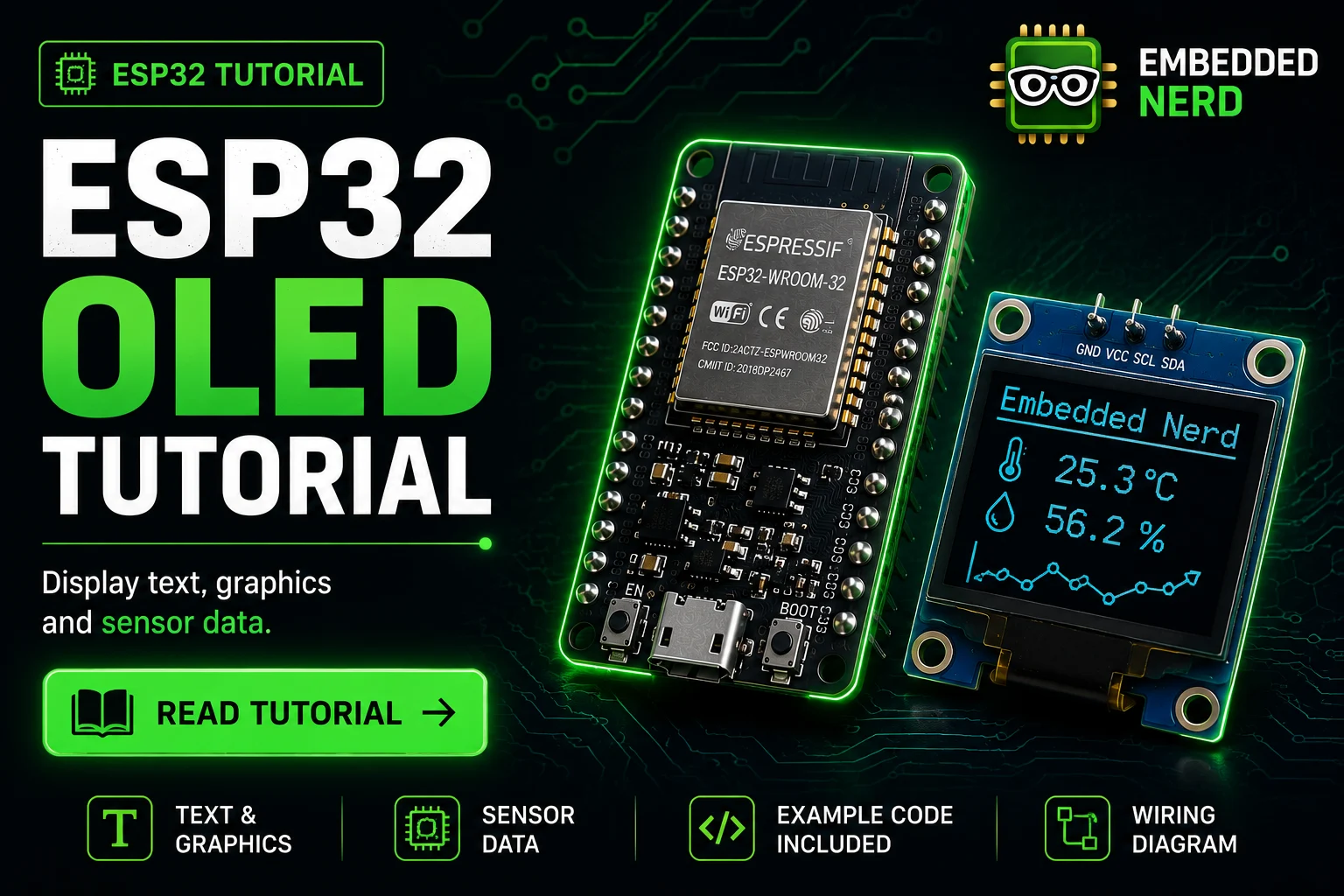
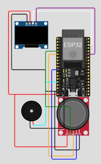
OLED Wiring
The SSD1306 communicates using the I²C interface.
| OLED | ESP32 |
|---|---|
| VCC | 3V3 |
| GND | GND |
| SDA | GPIO21 |
| SCL | GPIO22 |
The joystick remains connected as in the previous chapters.
Installing the Required Libraries
Open:
Sketch

↓

Include Library

↓

Manage Libraries
Install:
- Adafruit SSD1306
- Adafruit GFX Library
These libraries greatly simplify drawing text, graphics, and menus.
Menu Structure
Our menu will contain four items.
>Main Screen

 Settings

 Servo Test

 About
The highlighted item represents the current selection.
Moving the joystick:
- Up → Previous item
- Down → Next item
Pressing the joystick button selects the highlighted option.
Defining the Menu
const char* menuItems[] =
{
    "Main Screen",
    "Settings",
    "Servo Test",
    "About"
};

const int totalItems = 4;

int selectedItem = 0;
This structure makes it easy to add or remove menu options.
Drawing the Menu
display.clearDisplay();

for(int i = 0; i < totalItems; i++)
{
    if(i == selectedItem)
    {
        display.print(">");
    }
    else
    {
        display.print(" ");
    }

    display.println(menuItems[i]);
}

display.display();
The arrow indicates the currently selected menu item.
Reading the Joystick
We’ll use the calibrated Y-axis value.
int y =
readAverage(yAxisPin);

y -= centerY;
Now apply the dead zone.
if(abs(y) < deadZone)
{
    y = 0;
}
Moving Through the Menu
If the joystick moves upward:
if(y > 500)
{
    selectedItem--;

    delay(180);
}
Moving downward:
if(y < -500)
{
    selectedItem++;

    delay(180);
}
The short delay prevents the menu from scrolling too quickly.
Preventing Index Errors
Always keep the selected item inside the valid range.
if(selectedItem < 0)
{
    selectedItem = totalItems - 1;
}

if(selectedItem >= totalItems)
{
    selectedItem = 0;
}
This creates a circular menu.
Example:
About

↓

Main Screen
and
Main Screen

↑

About
This feels much more natural than stopping at the first or last item.
Selecting an Item
The joystick button acts as the Enter key.
if(digitalRead(buttonPin) == LOW)
{
    Serial.println(menuItems[selectedItem]);

    delay(300);
}
Later, each menu item can launch a different application or settings page.
Creating a Better User Experience
Instead of instantly changing the selection every time the joystick moves slightly, wait until the joystick returns to the center before accepting another movement.
Pseudo-code:
Move joystick

↓

Change menu

↓

Wait until joystick returns

↓

Accept next movement
This prevents accidental skipping of multiple items.
Highlighting the Selected Item
The SSD1306 library allows you to invert colours.
Example:
display.fillRect(0, lineY, 128, 10, WHITE);

display.setTextColor(BLACK);

display.setCursor(2, lineY + 1);

display.print(menuItems[i]);

display.setTextColor(WHITE);
The selected item appears highlighted, similar to commercial user interfaces.
Adding Icons
You can further improve the menu by displaying small bitmap icons.
Example:
⚙ Settings

🎮 Servo Test

ℹ About
Icons make navigation faster and more intuitive.
Creating Submenus
A real application usually contains more than one page.
For example:
Main Menu

↓

Settings

↓

Brightness

↓

Contrast

↓

Wi-Fi
Instead of using a single variable, define an application state.
enum Screen
{
    MAIN_MENU,
    SETTINGS,
    SERVO,
    ABOUT
};

Screen currentScreen = MAIN_MENU;
Switching between screens becomes much cleaner.
Practical Applications
The same menu structure can be reused in many projects.
Examples include:
- Temperature controllers
- Smart thermostats
- Greenhouse automation
- Data loggers
- Oscilloscopes
- Battery monitors
- Electronic loads
- Home automation dashboards
Once you’ve built one menu system, you can easily adapt it to future projects.
Troubleshooting
OLED Remains Blank
Check:
- I²C wiring
- OLED address (0x3C or 0x3D)
- Library installation
- SDA and SCL pins
Running an I²C scanner sketch is a quick way to verify the display address.
Menu Scrolls Too Quickly
Increase the delay or implement joystick release detection before allowing another movement.
Random Menu Movements
Possible causes:
- Dead zone too small
- No averaging filter
- Poor joystick calibration
Increasing the dead zone to around 40–60 ADC counts usually solves the issue.
Flickering Display
Avoid calling display.display() more often than necessary.
Only refresh the screen when something changes.
This reduces flicker and improves overall performance.
Tip
Redrawing the OLED only when the menu changes significantly reduces I²C traffic and makes the interface feel much smoother.
What’s Next?
So far, we’ve built several practical applications using the joystick:
- Reading analog values
- Detecting button presses
- Controlling a servo
- Driving a DC motor
- Navigating OLED menus
In the next chapter, we’ll explore advanced joystick techniques, including exponential response curves, sensitivity adjustment, custom mapping functions, acceleration, and wireless control over Bluetooth and Wi-Fi. These techniques are commonly used in drones, RC transmitters, gaming controllers, and industrial control systems.
Advanced Joystick Techniques
By now, you’ve learned how to read the joystick, calibrate it, eliminate noise, and use it to control servos, motors, and OLED menus.
While these techniques are sufficient for many projects, professional embedded systems often apply additional signal processing to improve responsiveness and user experience.
In this chapter, you’ll learn several advanced techniques that can be adapted to almost any joystick-controlled project.
These include:
- Sensitivity adjustment
- Exponential response curves
- Low-pass filtering
- Median filtering
- Percentage conversion
- Velocity mapping
- Angle mapping
- Diagonal movement detection
- Wireless joystick communication
These concepts are widely used in commercial products ranging from RC transmitters to industrial machinery.
Adjusting the Joystick Sensitivity
Sometimes a joystick feels too sensitive.
Small movements may produce large responses.
Instead of changing the hardware, we can simply reduce the sensitivity in software.
For example:
normalizedX /= 2;
normalizedY /= 2;
Now moving the joystick halfway produces a much smaller output.
This is useful for:
- Camera control
- Robot arms
- Precision positioning
- CNC jogging
Increasing the Sensitivity
The opposite is also possible.
normalizedX *= 2;
normalizedY *= 2;
Always remember to constrain the final value.
normalizedX = constrain(normalizedX,-2048,2047);
This technique makes the joystick feel much more responsive.
Linear Response
Until now we’ve assumed the joystick behaves linearly.
Joystick Movement

↓

Motor Speed
A small movement produces a small speed increase.
A large movement produces a large speed increase.
This is called a linear response.
It is simple and predictable.
Exponential Response (Expo)
Many radio-controlled aircraft and drones use an exponential response curve.
Near the center, movement becomes less sensitive.
Near the edges, movement becomes much more aggressive.
This provides:
- Better precision
- Smoother control
- Easier hovering
- Better aiming
Example:
float input =
normalizedX / 2048.0;

float expo = input * input * input;

int output =
expo * 2048;
Near the center:
Very Smooth
Near the edges:
Very Fast
Professional RC transmitters almost always offer adjustable exponential curves.
Percentage Conversion
Sometimes raw ADC values are difficult to interpret.
Converting them into percentages makes debugging much easier.
Example:
int percentage =
map(xValue,0,4095,0,100);
Result:
0%

↓

100%
Or centered around zero:
int percentage =
map(normalizedX,-2048,2047,-100,100);
Now the joystick reports:
Left

↓

-100%

Center

↓

0%

Right

↓

100%
This representation is ideal for user interfaces.
Velocity Mapping
Many robots are controlled using speed rather than position.
Convert the joystick reading into a velocity.
int speed =
map(normalizedY,-2048,2047,-255,255);
Now:
Forward

↓

Positive Speed

Reverse

↓

Negative Speed
This is exactly how differential-drive robots are controlled.
Angle Mapping
Servos usually require angles.
Example:
int angle =
map(xValue,0,4095,0,180);
Or limit the travel:
map(xValue,0,4095,30,150);
Reducing the mechanical range often improves reliability.
PWM Mapping
LED brightness and motor speed are usually controlled using PWM.
int pwm =
map(abs(normalizedY),0,2048,0,255);
Now pushing the joystick further increases brightness or motor speed.
Low-Pass Filtering
A Moving Average filter reduces noise effectively.
However, another popular technique is the Low-Pass Filter.
Formula:
Filtered

=

Previous

+

(New-Previous)

×

Alpha
Example:
filteredX =
filteredX +
0.2 * (rawX-filteredX);
Advantages:
- Smooth movement
- Fast response
- Very little memory
This technique is widely used in flight controllers.
Median Filtering
Occasionally an ADC produces a sudden incorrect reading.
Example:
2048

2050

4095

2047

2051
The value 4095 is clearly incorrect.
A median filter removes these spikes automatically.
Instead of averaging, it selects the middle value.
Median filters are especially useful in electrically noisy environments.
Detecting Diagonal Movement
Many games require eight directions.
Instead of only:
- Up
- Down
- Left
- Right
we also detect:
- Up Left
- Up Right
- Down Left
- Down Right
Example:
if(x>500 && y>500)
{
    Serial.println("UP RIGHT");
}
The same logic applies to the remaining diagonal directions.
Variable Dead Zone
Earlier we used a fixed dead zone.
Professional controllers sometimes adjust it dynamically.
For example:
Small movements
↓
Small dead zone
Large movements
↓
Larger dead zone
This creates a smoother user experience.
Using the Joystick as a Mouse
The ESP32 can emulate a Bluetooth HID mouse.
Joystick movement controls the cursor.
Button press becomes the left mouse click.
Possible mapping:
| Joystick | Mouse |
|---|---|
| X | Cursor Left/Right |
| Y | Cursor Up/Down |
| SW | Left Click |
This is an excellent beginner Bluetooth project.
Bluetooth Game Controller
Instead of acting as a mouse, the ESP32 can emulate a Bluetooth gamepad.
The joystick axes become:
Left Analog Stick
while the button becomes:
Button A
Computers, Android devices, and many game consoles can recognise the ESP32 as a wireless controller.
ESP-NOW Remote Control
ESP-NOW is a low-latency wireless protocol developed by Espressif.
One ESP32 reads the joystick.
Another ESP32 receives the commands.
Advantages include:
- No Wi-Fi router required
- Very low latency
- Low power consumption
- Excellent reliability
This is ideal for:
- Robots
- RC vehicles
- Smart home remotes
- Wireless controllers
Wi-Fi Robot Control
Instead of transmitting commands over ESP-NOW, the joystick can send data through Wi-Fi.
Possible applications include:
- Mobile robots
- Home automation
- IoT devices
- Camera systems
- Remote monitoring
The ESP32 can publish joystick data using:
- HTTP
- MQTT
- WebSocket
allowing any connected device to receive the commands.
Practical Ideas
Now that you understand advanced joystick processing, consider trying some of these projects:
- Pan-Tilt camera
- Bluetooth game controller
- Wireless robot
- CNC pendant
- Smart home remote
- MIDI controller
- Digital drawing tablet
- RC transmitter
- Camera gimbal
- Electronic Etch-A-Sketch
These projects build directly upon the techniques you’ve learned throughout this tutorial.
Pro Tip
Most professional joystick applications never use raw ADC readings directly. They combine calibration, filtering, dead zones, response curves, and value mapping to create smooth, predictable, and intuitive controls.
Performance Optimization & Best Practices
The examples presented throughout this guide are designed to be easy to understand.
However, when developing larger ESP32 applications, a few additional techniques can significantly improve performance, responsiveness, and reliability.
This section introduces several best practices commonly used in professional embedded systems.
Although not all of them are necessary for beginner projects, understanding these concepts will help you write cleaner and more scalable code.
Avoid Blocking Code
One of the most common beginner mistakes is relying heavily on:
delay();
For example:
delay(500);
While simple, this completely stops the processor for half a second.
During this time the ESP32 cannot:
- Read the joystick
- Update the OLED
- Receive Wi-Fi packets
- Process Bluetooth events
- Read sensors
As projects become more complex, excessive use of delay() quickly becomes a limitation.
Use millis() Instead
A better approach is timing events using:
millis()
Example:
unsigned long previous = 0;

const int interval = 20;

void loop()
{
    if(millis() - previous >= interval)
    {
        previous = millis();

        readJoystick();
    }
}
Advantages include:
-
Responsive user interface
-
Smooth multitasking
-
Better Wi-Fi performance
-
Easier project expansion
This technique is considered standard practice in Arduino programming.
Read the ADC Only When Necessary
Many beginners call:
analogRead();
multiple times inside the same loop.
Example:
if(analogRead(pin)>2000)
followed by:
Serial.println(analogRead(pin));
Each call performs a new ADC conversion.
Instead:
int value = analogRead(pin);
Use the stored value throughout the loop.
This reduces unnecessary ADC conversions and improves consistency.
Apply Filtering Before Processing
Always process the signal in the correct order.
Recommended pipeline:
Read ADC

↓

Filtering

↓

Calibration

↓

Dead Zone

↓

Normalization

↓

Application Logic
Keeping this sequence consistent makes your code easier to understand and maintain.
Use Meaningful Variable Names
Instead of:
int x;

int y;
prefer:
int joystickX;

int joystickY;
Similarly:
servoAngle

motorSpeed

centerX

filteredY
Descriptive names improve readability, especially in larger projects.
Organize Your Code into Functions
Rather than placing everything inside loop(), divide your program into small reusable functions.
Example:
readJoystick();

filterSignal();

updateServo();

updateDisplay();

checkButton();
Benefits include:
- Easier debugging
- Better readability
- Reusable code
- Simpler testing
Keep Constants Together
Instead of scattering configuration values throughout the code:
40

180

2048

10
declare them once.
Example:
const int deadZone = 40;

const int maxAngle = 180;

const int samples = 10;
Changing project parameters later becomes much easier.
Constrain Output Values
Whenever values are mapped or scaled, limit the output range.
Example:
servoAngle =
constrain(servoAngle,0,180);
This prevents unexpected behaviour caused by invalid values.
Avoid Floating Inputs
Unused digital inputs should never be left floating.
Always configure them using:
INPUT_PULLUP
or
INPUT_PULLDOWN
depending on the application.
Floating inputs often produce random behaviour that is difficult to diagnose.
Choose ADC1 Pins
Whenever possible, connect analog sensors to ADC1 GPIOs.
Advantages:
- Compatible with Wi-Fi
- More reliable
- Recommended by Espressif
This simple decision can prevent many future debugging sessions.
Use External Power for Motors
Servos and DC motors generate electrical noise.
Always power them separately from the ESP32.
Remember:
Separate Supply

↓

Common Ground
This greatly improves stability.
Minimize OLED Updates
Updating an OLED display hundreds of times per second wastes CPU time and increases I²C traffic.
Instead:
Only refresh the display when something changes.
This produces:
- Smoother menus
- Less flicker
- Lower CPU usage
Consider FreeRTOS for Larger Projects
One of the ESP32’s biggest advantages is built-in FreeRTOS support.
As projects become more advanced, different tasks can run independently.
Example:
Task 1
↓
Read joystick
Task 2
↓
Update OLED
Task 3
↓
Control motors
Task 4
↓
Wi-Fi communication
This keeps the application responsive even under heavy workloads.
Although FreeRTOS is beyond the scope of this tutorial, it is worth exploring in future projects.
Calibrate Every Time the Device Starts
Never assume every joystick behaves identically.
Running a quick calibration routine during startup ensures consistent behaviour across different modules.
The calibration process only takes a fraction of a second but greatly improves accuracy.
Document Your Code
Good comments explain why something is done, not merely what the code already says.
Instead of:
// Read X
prefer:
// Read and average the X-axis to reduce ADC noise
Future-you will appreciate the extra context.
Test Incrementally
When building larger projects, add one feature at a time.
For example:
- Read the joystick
- Verify Serial output
- Add filtering
- Add calibration
- Add servo control
- Add OLED
- Add Wi-Fi
This incremental approach makes debugging far easier than introducing multiple changes simultaneously.
Summary of Best Practices
Following these recommendations will make your projects:
✔ More stable
✔ Easier to maintain
✔ More responsive
✔ Easier to debug
✔ More scalable
✔ Ready for future expansion
Professional embedded software is rarely more complicated because of the hardware—it is usually more robust because it follows good engineering practices from the beginning.
Best Practice
Focus on writing code that is clear, modular, and reliable rather than simply making it work. A well-structured project is much easier to debug, extend, and reuse in future designs.
Troubleshooting Guide
Even a simple circuit can occasionally behave in unexpected ways.
Fortunately, most joystick-related issues are caused by incorrect wiring, unsuitable GPIO selection, or missing software configuration.
This section lists the most common problems together with their causes and solutions.
If your project isn’t behaving as expected, work through the following checklist before replacing any hardware.
Problem: X and Y Always Read Zero
Symptoms
X = 0

Y = 0
regardless of joystick movement.
Possible Causes
- No power supplied to the joystick
- Incorrect GPIO numbers
- Broken jumper wire
- Loose breadboard connection
- Missing common ground
Solution
Verify:
- VCC → 3.3V
- GND → GND
- VRx → GPIO34
- VRy → GPIO35
Measure the voltage between VCC and GND with a multimeter.
You should read approximately:
3.3V
Problem: Readings Always Stay Near 4095
Symptoms
4095

4095

4095
Possible Causes
- VRx or VRy shorted to VCC
- Incorrect wiring
- Damaged joystick module
Solution
Disconnect the joystick.
Measure the voltage on the VRx and VRy pins while moving the stick.
The voltage should change smoothly between approximately:
0V

↓

3.3V
Problem: Values Jump Randomly
Symptoms
2030

2055

2012

2078

2040
Is this normal?
Small variations are completely normal.
Large jumps are not.
Possible Causes
- Poor USB power
- Long jumper wires
- Loose breadboard
- Electrical interference
- Poor-quality joystick
Solutions
✔ Use shorter wires
✔ Add a moving average filter
✔ Increase the dead zone
✔ Use a better USB cable
✔ Power the ESP32 from a stable supply
Problem: Button Never Changes State
Symptoms
Released

Released

Released
even while pressing the joystick.
Solution
Verify:
pinMode(buttonPin, INPUT_PULLUP);
Without the internal pull-up resistor the input floats.
Also check that the SW pin is connected correctly.
Problem: Button Is Always Pressed
Symptoms
Pressed

Pressed

Pressed
Possible Causes
- SW connected directly to GND
- Wrong GPIO
- Short circuit
Solution
Disconnect the SW wire.
The reading should immediately change to:
Released
If not, inspect the wiring.
Problem: Center Value Isn’t 2048
Symptoms
2038

2061

2052
instead of exactly:
2048
Is this normal?
Yes.
Every joystick has manufacturing tolerances.
This is exactly why we implemented automatic calibration.
Never hard-code:
center = 2048;
Instead:
calibrateJoystick();
Problem: Servo Vibrates Constantly
Symptoms
The servo never stops moving.
Causes
- No dead zone
- No filtering
- Poor power supply
- Mechanical load
Solution
Increase:
deadZone = 50;
or
deadZone = 60;
Also average multiple ADC readings before mapping the angle.
Problem: Servo Causes ESP32 Resets
Symptoms
Guru Meditation Error

Brownout Detector
or random restarts.
Cause
The servo is drawing too much current.
Solution
Never power the servo from the ESP32.
Instead use:
External 5V

↓

Servo

ESP32 GND

↓

Common Ground
Problem: Motor Doesn’t Spin
Verify
- Motor battery connected
- Driver enabled
- Common ground
- PWM output configured
- Motor driver powered
Most motor problems are actually power supply problems.
Problem: Robot Slowly Moves by Itself
Cause
Dead zone too small.
Solution
Increase the dead zone.
Example:
const int deadZone = 60;
Problem: OLED Menu Scrolls Automatically
Causes
- Dead zone too small
- No joystick calibration
- Reading raw ADC values
Solution
Use:
- Calibration
- Moving average
- Dead zone
before detecting movement.
Problem: Wi-Fi Breaks Analog Readings
Symptoms
The joystick suddenly stops working after enabling Wi-Fi.
Cause
ADC2 pins are being used.
Solution
Move the analog signals to ADC1 GPIOs:
- GPIO32
- GPIO33
- GPIO34
- GPIO35
- GPIO36
- GPIO39
These remain fully functional while Wi-Fi is active.
Problem: Readings Don’t Reach 0 or 4095
Example
210

↓

3890
instead of
0

↓

4095
Is this normal?
Yes.
Potentiometers rarely reach their theoretical limits.
Always calibrate the usable range instead of assuming perfect values.
Problem: Movement Feels Too Sensitive
Reduce the sensitivity.
Example:
normalizedX /= 2;
or use an exponential response curve.
Problem: Movement Feels Too Slow
Increase the sensitivity.
Example:
normalizedX *= 2;

normalizedX =
constrain(normalizedX,-2048,2047);
Problem: Servo Doesn’t Reach 180°
Different servos use different pulse widths.
Try:
myServo.attach(pin,500,2400);
or
myServo.attach(pin,550,2450);
depending on your servo model.
Problem: Analog Values Drift Over Time
Causes
- Temperature changes
- Potentiometer wear
- Supply voltage variation
Solution
Run the calibration routine each time the ESP32 starts.
For long-running applications, consider adding a manual recalibration option in the menu.
Problem: Joystick Works in One Direction Only
Check:
- Broken potentiometer
- Incorrect VRx/VRy wiring
- Damaged ADC pin
Swap the X and Y connections temporarily to determine whether the issue follows the joystick or the ESP32 GPIO.
Quick Diagnostic Checklist
Before replacing any hardware, verify the following:
✔ ESP32 powered correctly
✔ Joystick powered from 3.3V
✔ Common ground connected
✔ ADC1 GPIOs used
✔ INPUT_PULLUP enabled
✔ Calibration completed
✔ Dead zone implemented
✔ Moving average filter enabled
✔ Stable USB power supply
✔ Secure jumper wire connections
In most cases, one of these checks will identify the problem.
Pro Tip
When debugging hardware, change only one thing at a time. If you modify the wiring, code, and power supply simultaneously, it becomes much harder to determine which change fixed the issue.
Frequently Asked Questions (FAQ)
This section answers some of the most common questions about using the KY-023 analog joystick with the ESP32.
If you’re just getting started, you’ll likely find the answer to your question here.
1. Can I power the KY-023 from 5V?
Technically, yes.
However, it is strongly recommended to power the joystick from 3.3V when using an ESP32.
The ESP32 GPIOs are not 5V tolerant, and powering the joystick at 5V may produce analog voltages that exceed the maximum safe input voltage.
Powering the module from 3.3V ensures the VRx and VRy outputs always remain within the ESP32’s safe operating range.
2. Which GPIOs should I use?
For analog inputs, use ADC1 pins whenever possible.
Recommended GPIOs are:
| GPIO | ADC | Recommended |
|---|---|---|
| GPIO32 | ADC1 | ✔ |
| GPIO33 | ADC1 | ✔ |
| GPIO34 | ADC1 | ✔ Excellent |
| GPIO35 | ADC1 | ✔ Excellent |
| GPIO36 | ADC1 | ✔ |
| GPIO39 | ADC1 | ✔ |
Avoid ADC2 pins if your project uses Wi-Fi.
3. Why should I avoid ADC2?
ADC2 shares hardware resources with the Wi-Fi subsystem.
When Wi-Fi is enabled, analog readings from ADC2 pins may become unavailable or unreliable.
Using ADC1 avoids this limitation and makes your project easier to expand in the future.
4. Why isn’t the center value exactly 2048?
Because no joystick is perfectly manufactured.
Typical center readings are:
2034

2049

2057

2062
This is completely normal.
Always calibrate the joystick during startup instead of assuming a fixed center value.
5. What dead zone should I use?
A good starting point is:
const int deadZone = 40;
General recommendations:
| Dead Zone | Behaviour |
|---|---|
| 20 | Very sensitive |
| 40 | Recommended |
| 60 | Smooth |
| 80 | Less sensitive |
The ideal value depends on your joystick and application.
6. Do I need filtering?
For simple experiments:
No.
For real projects:
Absolutely.
Filtering significantly reduces:
- ADC noise
- Servo jitter
- Robot drift
- OLED menu instability
Even a simple moving average produces much smoother control.
7. Should I use a Moving Average or a Low-Pass Filter?
Both work well.
Moving Average
Advantages:
- Easy to understand
- Excellent noise reduction
Disadvantages:
- Slight delay
Low-Pass Filter
Advantages:
- Very smooth
- Faster response
- Minimal memory usage
Disadvantages:
- Requires floating-point calculations
For beginners, the Moving Average filter is usually the best choice.
8. Why doesn’t the joystick reach 0 or 4095?
Potentiometers have manufacturing tolerances.
Typical values might be:
Left

↓

135

Right

↓

3920
This is normal.
Never assume the full ADC range is available.
Calibration is the correct solution.
9. Can I control two servos?
Yes.
A common approach is:
| Axis | Servo |
|---|---|
| X | Pan |
| Y | Tilt |
This creates a simple pan-tilt mechanism for cameras, laser pointers, or sensors.
10. Can I control a robot?
Yes.
In fact, this is one of the most common applications.
Typical mapping:
| Axis | Function |
|---|---|
| Y | Forward / Reverse |
| X | Steering |
This allows smooth proportional control of a differential-drive robot.
11. Can I use the joystick for menu navigation?
Absolutely.
This is one of the best alternatives to multiple push buttons.
Typical mapping:
| Movement | Action |
|---|---|
| Up | Previous item |
| Down | Next item |
| Press | Select |
This approach is commonly used in embedded devices with OLED displays.
12. Does the joystick require external resistors?
No.
The module already contains the required potentiometers.
For the push button, simply enable the ESP32’s internal pull-up resistor:
pinMode(buttonPin, INPUT_PULLUP);
No additional components are required.
13. Can I use interrupts for the button?
Yes.
Although polling is perfectly adequate for most projects, the push button can also trigger an interrupt.
Example:
attachInterrupt(
    digitalPinToInterrupt(buttonPin),
    buttonISR,
    FALLING
);
Keep the interrupt service routine as short as possible.
14. Can I use MicroPython instead of Arduino IDE?
Yes.
The joystick works equally well with:
- Arduino IDE
- PlatformIO
- ESP-IDF
- MicroPython
Only the software syntax changes.
The hardware connections remain exactly the same.
15. Can I use this joystick with ESP32-S3, ESP32-C3, or ESP32-C6?
Yes.
The overall principle is identical.
However, the available ADC GPIOs differ between ESP32 families.
Always consult the pinout of your specific development board before selecting the analog input pins.
16. Can I connect multiple joysticks?
Yes.
Each joystick requires:
- Two analog inputs
- One digital input
For example:
| Device | GPIOs Required |
|---|---|
| One Joystick | 3 |
| Two Joysticks | 6 |
This is useful for dual-stick game controllers and advanced robotic systems.
17. Why does my servo shake even after calibration?
Possible causes include:
- Power supply instability
- Mechanical load
- Servo quality
- Dead zone too small
- No signal filtering
Using an external power supply together with filtering and a dead zone usually eliminates the problem.
18. Can I build a wireless controller?
Yes.
The ESP32 supports several wireless communication methods.
Popular choices include:
- Bluetooth Classic
- Bluetooth Low Energy (BLE)
- ESP-NOW
- Wi-Fi
- MQTT
- WebSocket
This makes it possible to create wireless robots, remote controls, and custom game controllers.
19. Which joystick module should I buy?
The KY-023 is an excellent choice because it is:
- Inexpensive
- Widely available
- Easy to interface
- Compatible with 3.3V systems
- Suitable for beginners
Higher-end industrial joysticks are available, but the KY-023 offers excellent value for most hobby and educational projects.
20. What should I build next?
Once you’re comfortable with the basics, consider extending your project with one of the following ideas:
- Bluetooth gamepad
- Pan-tilt camera
- Wi-Fi robot
- ESP-NOW remote controller
- RC transmitter
- CNC pendant
- Smart home controller
- Robot arm
- Camera gimbal
- OLED user interface
- MIDI controller
- Electronic drawing pad
Each of these projects builds directly on the techniques covered in this tutorial.
Quick Reference
| Feature | Recommendation |
|---|---|
| Supply Voltage | 3.3V |
| ADC Pins | ADC1 |
| Dead Zone | 40–60 |
| Filter | Moving Average (8–10 samples) |
| ADC Resolution | 12-bit |
| Servo Power | External 5V |
| Recommended IDE | Arduino IDE |
| Recommended Board | ESP32 Dev Module |
Summary
The KY-023 is a simple module, but when combined with calibration, filtering, dead zones, and proper signal processing, it becomes a powerful input device suitable for robotics, automation, gaming, and industrial control systems. Mastering these techniques will allow you to reuse the same code and design principles in many future ESP32 projects.
Recommended Hardware
Throughout this tutorial, we’ve used a small selection of affordable components that are widely available and suitable for both beginners and experienced makers.
Investing in quality components not only makes your projects more reliable but also saves time when troubleshooting.
Below are the parts we recommend for this project.
| Product | Why We Recommend It | Link |
|---|---|---|
| ESP32 Dev Board | Powerful Wi-Fi and Bluetooth microcontroller with a 240 MHz dual-core CPU | Amazon Affiliate |
| KY-023 Analog Joystick | Low-cost analog joystick with two potentiometers and a push button | Amazon Affiliate |
| SG90 Micro Servo | Ideal for learning motion control and robotics | Amazon Affiliate |
| SSD1306 OLED Display (128×64) | Perfect for menus, sensors, and user interfaces | Amazon Affiliate |
| L298N Motor Driver | Beginner-friendly H-bridge for DC motors | Amazon Affiliate |
| TB6612FNG Motor Driver | More efficient alternative to the L298N | Amazon Affiliate |
| Breadboard Kit | Reusable prototyping platform | Amazon Affiliate |
| Premium Jumper Wires | Reliable electrical connections | Amazon Affiliate |
| USB Power Supply (5V 2A) | Stable power for ESP32 projects | Amazon Affiliate |
Why These Components?
Although many alternatives exist, these modules have several advantages.
They are:
- Affordable
- Easy to find
- Well documented
- Supported by large communities
- Compatible with hundreds of ESP32 projects
As you continue learning, you’ll find yourself reusing these same components again and again.
Project Ideas
Now that you’ve mastered the basics of the KY-023 joystick, try extending what you’ve learned into larger projects.
Here are a few ideas.
Beginner Projects
- LED Brightness Controller
- Servo Position Controller
- OLED Menu Navigation
- RGB LED Mixer
- Digital Volume Knob
- Camera Pan Controller
Intermediate Projects
- Bluetooth Gamepad
- ESP-NOW Remote Controller
- Differential Drive Robot
- Two-Axis Camera Platform
- Electronic Drawing Pad
- MIDI Controller
- CNC Pendant
Advanced Projects
- Robot Arm Controller
- Wi-Fi Controlled Robot
- Camera Gimbal
- Drone Ground Station
- Smart Home Dashboard
- Industrial Control Panel
- Autonomous Vehicle Manual Override
Each of these projects builds directly upon the concepts introduced in this tutorial.
Continue Learning
If you enjoyed this project, you may also like these tutorials on Embedded Nerd.
Recommended ESP32 Tutorials
- Getting Started with the ESP32
- ESP32 GPIO Explained
- ESP32 PWM Tutorial
- ESP32 ADC Complete Guide
- ESP32 Interrupts Tutorial
- ESP32 Servo Motor Guide
- ESP32 DC Motor Control
- ESP32 I²C Scanner
- ESP32 OLED Display Tutorial
- ESP32 Bluetooth Guide
- ESP32 Wi-Fi Tutorial
- ESP32 ESP-NOW Guide
These tutorials build naturally on the techniques you’ve learned here and will help you create more advanced embedded systems.
Learning Path
If you’re new to the ESP32 ecosystem, we recommend following this order.
- ESP32 Basics
- Digital Inputs and Outputs
- Analog Inputs (ADC)
- PWM Outputs
- Interrupts
- I²C Communication
- OLED Displays
- Servo Motors
- DC Motor Drivers
- Bluetooth
- Wi-Fi Networking
- ESP-NOW
- Robotics Projects
By following this sequence, each new topic builds on knowledge you’ve already gained.
Source Code
The complete Arduino sketch used throughout this tutorial is available for download.
The code includes:
- Hardware initialization
- ADC configuration
- Automatic calibration
- Moving Average filtering
- Dead zone implementation
- Servo control
- DC motor example
- OLED navigation example
Feel free to modify and adapt the code for your own projects.
Downloads
To help you get started quickly, we’ve also prepared several resources.
Available downloads include:
- Complete Arduino Sketch
- Wiring Diagram
- High-Resolution Pinout
- OLED Menu Example
- Servo Project
- Motor Control Project
- PDF Wiring Reference
These resources can save time while building your own projects.
Before You Go…
If this tutorial helped you build your project, consider exploring the rest of the ESP32 section on Embedded Nerd.
Our goal is to create practical, beginner-friendly tutorials that not only explain how something works, but also why it works.
Every project is designed to be reusable, expandable, and based on real-world engineering practices.
Whether you’re building a robot, an IoT device, or your first embedded system, the same techniques you learned here will continue to be useful.
Conclusion
The KY-023 Analog Joystick may appear to be a simple module, but as you’ve seen throughout this guide, it is an incredibly versatile input device capable of powering a wide range of interactive ESP32 projects.
From reading two analog voltages to controlling robots, navigating OLED menus, operating servo motors, and transmitting commands wirelessly, the same joystick can become the heart of countless embedded systems.
More importantly, you’ve learned that building reliable projects is about much more than simply calling analogRead().
Professional embedded applications process raw sensor data before using it.
Throughout this tutorial, you’ve implemented many of the same techniques used in commercial products, including:
- Automatic calibration
- Dead zone compensation
- Moving average filtering
- Low-pass filtering concepts
- Signal normalization
- Direction detection
- Speed mapping
- Servo control
- DC motor control
- OLED menu navigation
- Advanced response curves
- Wireless control concepts
These techniques dramatically improve the quality, stability, and responsiveness of joystick-controlled applications.
Although the KY-023 is inexpensive, the programming concepts you’ve learned apply equally well to industrial joysticks costing hundreds of dollars.
Once you understand how to process analog inputs correctly, you’ll find the same principles appearing in many other areas of embedded engineering.
Examples include:
- Position sensors
- Potentiometers
- Analog triggers
- Force-sensitive resistors
- Hall-effect sensors
- Industrial control levers
- Flight controllers
- Automotive electronics
In other words, this tutorial is about much more than a joystick.
It introduces the foundations of analog signal processing on the ESP32.
What You’ve Learned
By completing this guide, you can now confidently:
✔ Interface the KY-023 Analog Joystick with an ESP32
✔ Read analog values using the ESP32 ADC
✔ Configure GPIOs correctly
✔ Understand ADC resolution and attenuation
✔ Calibrate the joystick automatically
✔ Eliminate noise using software filtering
✔ Apply dead zones for stable control
✔ Convert raw ADC values into meaningful data
✔ Detect movement direction
✔ Control servo motors smoothly
✔ Drive DC motors proportionally
✔ Navigate OLED menus
✔ Build reusable menu systems
✔ Improve responsiveness using advanced processing techniques
✔ Design projects that are easier to expand and maintain
These skills form an excellent foundation for more advanced ESP32 development.
Where to Go Next
Once you’ve mastered the KY-023 joystick, there are countless opportunities to expand your knowledge.
Some excellent next steps include:
- Building a Bluetooth game controller
- Creating an ESP-NOW wireless remote
- Designing a differential-drive robot
- Developing a robotic arm
- Controlling a pan-tilt camera
- Creating an OLED-based settings interface
- Building a CNC jog controller
- Developing a MIDI controller
- Creating a smart home control panel
Each of these projects builds directly on the concepts you’ve learned in this tutorial.
As your confidence grows, you’ll discover that the joystick becomes just one of many reusable input devices in your embedded toolbox.
Continue Exploring ESP32
The ESP32 is one of the most capable and affordable microcontrollers available today.
Its combination of:
- Wi-Fi
- Bluetooth
- Fast dual-core processor
- Multiple ADC channels
- PWM outputs
- Timers
- Touch sensors
- Rich communication interfaces
makes it suitable for an enormous variety of applications.
Whether you’re interested in robotics, IoT, automation, wearable devices, sensor networks, or consumer electronics, the ESP32 provides an excellent platform for learning and experimentation.
Mastering one peripheral at a time is one of the fastest ways to become comfortable with embedded development.
The joystick you’ve explored in this guide is an important step along that journey.
Build, Experiment, Improve
One of the best ways to learn embedded systems is by experimenting.
Don’t be afraid to modify the example code.
Try changing the dead zone.
Experiment with different filters.
Adjust the response curve.
Control multiple servos.
Drive larger motors.
Create your own menu system.
Add wireless communication.
Every small improvement teaches you something new.
Engineering is an iterative process, and each project you build expands your understanding.
The examples presented throughout this guide are intended to serve as a solid foundation for your own ideas rather than finished products.
Final Thoughts
Learning embedded systems can feel overwhelming at first.
There are microcontrollers, sensors, communication protocols, displays, motors, drivers, and countless programming techniques to explore.
The key is to learn one concept at a time.
Projects like this demonstrate how a handful of inexpensive components can teach valuable engineering principles that apply far beyond a single tutorial.
If you’ve followed this guide from beginning to end, you’ve already taken an important step toward becoming a more confident ESP32 developer.
Keep experimenting.
Keep building.
Keep improving your code.
Most importantly, enjoy the process.
Every successful project starts with curiosity.
Thank You for Reading
Thank you for following this tutorial.
We hope it has helped you better understand both the KY-023 Analog Joystick and the ESP32 platform.
If you enjoyed this guide, be sure to explore the other tutorials available on Embedded Nerd.
Our goal is to publish practical, in-depth guides that explain not only how to build electronics projects, but also why they work.
From Arduino and ESP32 to Raspberry Pi, sensors, displays, motors, communication protocols, and robotics, you’ll find step-by-step tutorials designed to help you build real-world projects with confidence.
Happy building!
See you in the next project.