The BMA400 is a low-power 3-axis digital accelerometer designed for applications where motion sensing and energy efficiency are important.
In this tutorial, you’ll learn how to connect a BMA400 breakout board to an ESP32 using I2C, install the Arduino library, read acceleration from the X, Y and Z axes, and verify that the sensor is working correctly.
The BMA400 is particularly interesting for battery-powered projects because it combines a 3-axis accelerometer with built-in motion-detection features, interrupts, orientation detection, tap detection, activity recognition, and step counting.
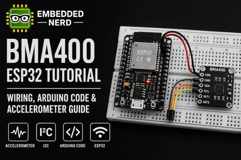
By the end of this guide, you’ll have a working BMA400 ESP32 setup that can be used as the foundation for motion sensing, wearable electronics, robotics, IoT devices, and low-power projects.
What Is the BMA400?
The BMA400 is a 3-axis digital accelerometer from Bosch Sensortec.
It measures acceleration along three perpendicular axes:
- X
- Y
- Z
Acceleration is measured in units of g, where 1 g represents approximately the acceleration caused by Earth’s gravity.
This means that a stationary sensor can measure approximately 1 g on the axis aligned with gravity, depending on the sensor orientation.
The BMA400 provides 12-bit acceleration measurements and supports selectable measurement ranges from ±2 g to ±16 g.
| Feature | BMA400 |
|---|---|
| Sensor type | 3-axis accelerometer |
| Resolution | 12-bit |
| Acceleration ranges | ±2 g, ±4 g, ±8 g, ±16 g |
| Interfaces | I2C and SPI |
| I2C addresses | 0x14 and 0x15 |
| Motion detection | Yes |
| Orientation detection | Yes |
| Tap detection | Yes |
| Step counting | Yes |
| FIFO | Yes |
| Interrupts | Yes |
The BMA400 is therefore more than a basic acceleration sensor. Several motion-related functions can be handled by the sensor itself instead of requiring the ESP32 to continuously process raw acceleration data.
Why Use the BMA400 with an ESP32?
The ESP32 is a powerful microcontroller with Wi-Fi and Bluetooth, but many embedded projects also need to operate from batteries.
The BMA400 is well suited to these applications because it was designed with low-power operation and hardware motion features in mind.
For example, a project can use the BMA400 to detect movement and then notify the ESP32 through an interrupt.
This can be useful for:
- Wearable electronics
- Motion-controlled interfaces
- Battery-powered IoT devices
- Activity trackers
- Security sensors
- Robotics
- Tilt detection
- Wake-on-motion applications
The sensor can therefore act as a low-power motion front end for the ESP32.
BMA400 vs MPU6050
If you’ve already worked with the MPU6050, the BMA400 may look similar at first because both devices can measure acceleration.
However, they are designed for different use cases.
The MPU6050 combines a 3-axis accelerometer and a 3-axis gyroscope, while the BMA400 is a 3-axis accelerometer with a strong focus on low-power operation and built-in motion features.
| Feature | BMA400 | MPU6050 |
|---|---|---|
| Accelerometer | 3-axis | 3-axis |
| Gyroscope | No | Yes |
| Interface | I2C / SPI | I2C |
| Acceleration range | ±2 / ±4 / ±8 / ±16 g | ±2 / ±4 / ±8 / ±16 g |
| Motion features | Extensive | More limited |
| Step counter | Yes | No dedicated step counter |
| Tap detection | Yes | No dedicated tap engine |
| Low-power focus | Strong | Lower |
If you need a gyroscope as well as an accelerometer, the MPU6050 is still a useful option.
If your project only needs acceleration and motion sensing, especially where low power is important, the BMA400 is worth considering.
You can learn more about the MPU6050 in our MPU6050 Arduino Guide.
For projects that require sensor calibration, our MPU6050 Calibration Guide also explains the importance of sensor offsets and calibration.
Required Hardware
For this tutorial you need:
| Component | Recommended Product | Buy |
|---|---|---|
| ESP32 Development Board | ESP32 DevKit V1 | 🛒 AliExpress |
| BMA400 Accelerometer Module | BMA400 Accelerometer Module | 🛒 AliExpress |
| Solderless Breadboard | Solderless Breadboard | — |
| Jumper Wires | Jumper Wires | — |
Some links on this page are affiliate links. If you purchase through them, Embedded Nerd may earn a small commission at no additional cost to you. This helps support the website and allows us to continue creating free tutorials and guides. Thank you for your support!
A breakout board is strongly recommended because the BMA400 sensor itself is a very small surface-mount component.
The breakout provides accessible pins that make it possible to connect the sensor directly to a breadboard.
Note: The BMA400 breakout used in this tutorial should be suitable for 3.3 V ESP32 logic. Always check the specifications of the exact breakout board you are using.
BMA400 Breakout Boards
The BMA400 is available on several breakout boards.
One example is the SparkFun Triple Axis Accelerometer Breakout - BMA400 (Qwiic).
SparkFun also provides a smaller Micro version.
When choosing a BMA400 breakout, check:
- I2C support
- Supply voltage
- Interrupt pins
- Board size
- Pull-up resistors
- Connector type
- Documentation
- Library support
For a first ESP32 project, an I2C breakout is usually the simplest choice.
BMA400 Pinout
The exact pin names depend on the breakout board.
A typical BMA400 breakout may expose:
- VDD
- VDDIO
- GND
- SDA
- SCL
- INT1
- INT2
Some boards also expose the pins required for SPI communication.
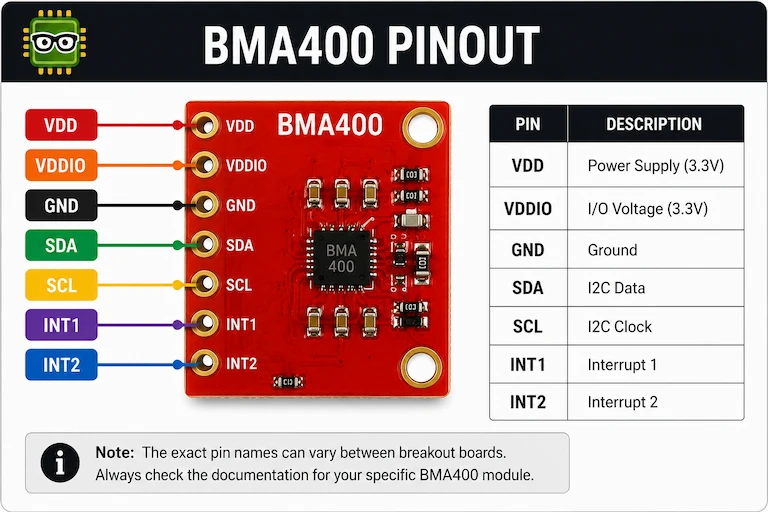
For the basic I2C tutorial, we only need:
- Power
- Ground
- SDA
- SCL
The interrupt pins are not required for the basic acceleration example.
BMA400 I2C Address
The BMA400 supports two I2C addresses:
| Address | Description |
|---|---|
0x14 |
Default |
0x15 |
Alternate |
The actual address depends on the configuration of the breakout board.
If the ESP32 cannot detect the sensor, checking the I2C address should be one of the first troubleshooting steps.
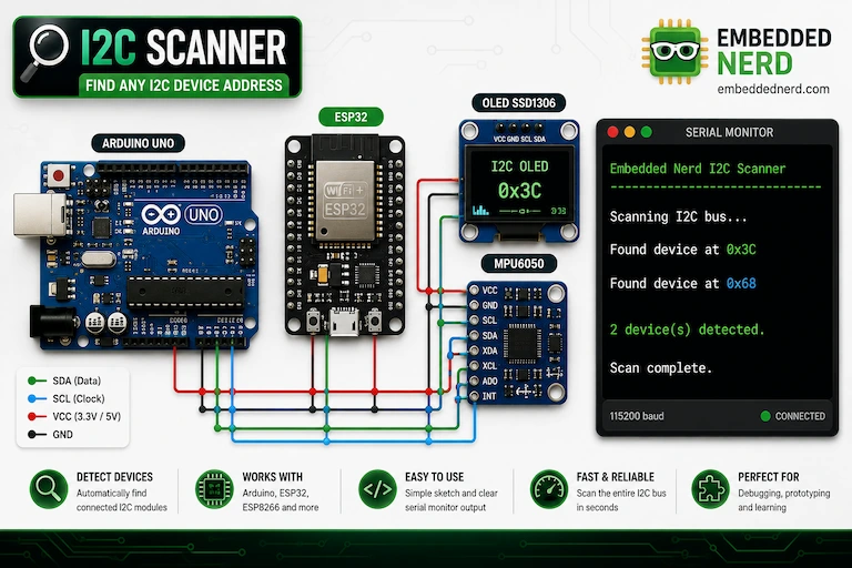
An I2C scanner is especially useful when working with sensors and displays.
Our I2C Scanner Tutorial explains how to detect I2C devices and identify their addresses.
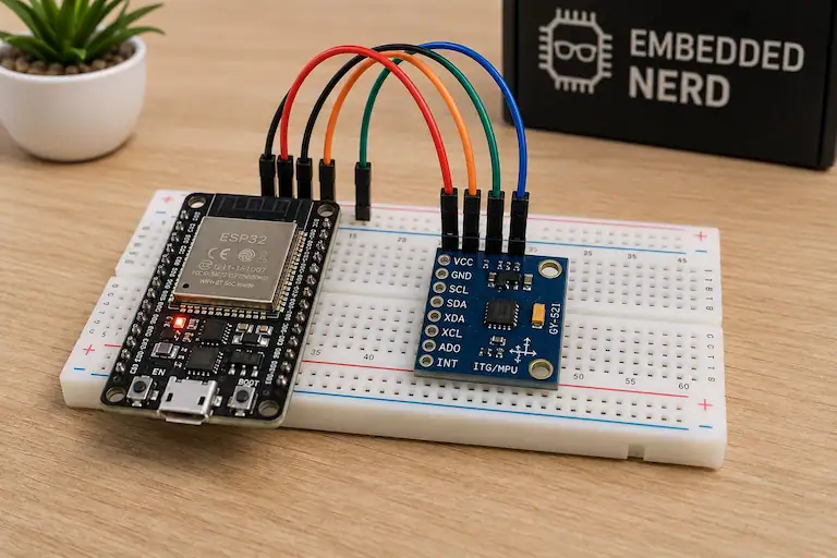
BMA400 ESP32 Wiring
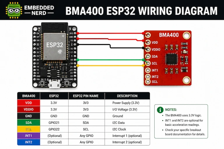
The BMA400 can communicate with the ESP32 using I2C.
For a typical ESP32 development board, the default I2C pins are:
| BMA400 | ESP32 |
|---|---|
| VDD / VCC | 3.3V |
| GND | GND |
| SDA | GPIO21 |
| SCL | GPIO22 |
Wiring Notes
The typical ESP32 I2C pins are:
SDA → GPIO21
SCL → GPIO22
GND → GND
VCC/VDD → 3.3V
However, breakout boards can differ in their power circuitry and pin naming.
Always check the documentation for the exact BMA400 module you are using.
If the breakout exposes both VDD and VDDIO, follow the breakout manufacturer’s wiring instructions rather than assuming that both pins can be connected identically.
Installing the BMA400 Arduino Library
The easiest way to use the BMA400 with Arduino is the SparkFun BMA400 Arduino Library.
The library provides an Arduino-friendly interface to the BMA400 and implements Bosch’s BMA400 API.
Arduino IDE
Open:
Sketch → Include Library → Manage Libraries
Search for:
SparkFun BMA400
Install the library provided by SparkFun.
The library includes examples for basic acceleration measurements as well as more advanced features.
BMA400 ESP32 Code Example
The following example initializes the BMA400 over I2C and continuously prints acceleration measured on all three axes.
#include <Wire.h>
#include "SparkFun_BMA400_Arduino_Library.h"

BMA400 accelerometer;

uint8_t i2cAddress = BMA400_I2C_ADDRESS_DEFAULT;

void setup()
{
  Serial.begin(115200);

  Wire.begin();

  Serial.println();
  Serial.println("BMA400 ESP32 Tutorial");
  Serial.println("Initializing BMA400...");

  while (accelerometer.beginI2C(i2cAddress) != BMA400_OK)
  {
    Serial.println("BMA400 not detected. Check wiring and I2C address.");
    delay(1000);
  }

  Serial.println("BMA400 connected!");
}

void loop()
{
  accelerometer.getSensorData();

  Serial.print("X: ");
  Serial.print(accelerometer.data.accelX, 3);
  Serial.print(" g");

  Serial.print(" | Y: ");
  Serial.print(accelerometer.data.accelY, 3);
  Serial.print(" g");

  Serial.print(" | Z: ");
  Serial.print(accelerometer.data.accelZ, 3);
  Serial.println(" g");

  delay(100);
}
The important sequence is:
- Start I2C.
- Initialize the BMA400.
- Request new sensor data.
- Read the X axis.
- Read the Y axis.
- Read the Z axis.
Understanding the Code
Wire.begin()
Wire.begin();
Initializes the ESP32 I2C interface.
On a typical ESP32 development board, the default pins are:
- SDA = GPIO21
- SCL = GPIO22
beginI2C()
accelerometer.beginI2C(i2cAddress);
Initializes communication with the BMA400.
The default address is represented by:
BMA400_I2C_ADDRESS_DEFAULT
The library also provides:
BMA400_I2C_ADDRESS_SECONDARY
for the alternate address.
getSensorData()
accelerometer.getSensorData();
Requests updated acceleration data from the sensor.
This needs to be called before reading the acceleration values.
Reading X, Y and Z
The acceleration values are available through:
accelerometer.data.accelX
accelerometer.data.accelY
accelerometer.data.accelZ
The library reports the acceleration values in g.
BMA400 Output
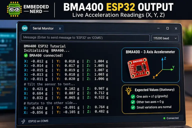
Open the Arduino Serial Monitor and select:
115200 baud
With the sensor stationary on a flat surface, one axis should normally be close to ±1 g, depending on the orientation of the board.
For example:
X: -0.012 g | Y: 0.018 g | Z: 1.004 g
X: -0.014 g | Y: 0.017 g | Z: 1.005 g
X: -0.015 g | Y: 0.019 g | Z: 1.007 g
These are illustrative values, not guaranteed measurements.
The exact readings depend on:
- Sensor orientation
- Sensor noise
- Mechanical mounting
- Power supply
- Configuration
- Calibration
The important observation is that a stationary sensor should measure approximately 1 g along the axis aligned with gravity.
Understanding the X, Y and Z Axes
The BMA400 measures acceleration independently along three axes.
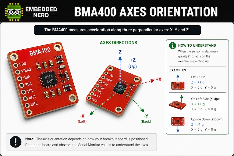
When the sensor is stationary, gravity provides a simple way to understand the axes.
For example, if the Z axis is pointing upward, the sensor will normally measure approximately:
X ≈ 0 g
Y ≈ 0 g
Z ≈ +1 g
If the board is turned upside down, the dominant axis will change sign.
Rotating the board onto its side moves the gravity component from one axis to another.
This is the basis of simple tilt and orientation detection.
What Happens When You Move the BMA400?
Try rotating the sensor slowly.
As the orientation changes, the acceleration values on X, Y and Z will change.
For example:
- Flat on a table → one axis is approximately ±1 g.
- Rotate 90 degrees → another axis becomes dominant.
- Turn the board upside down → the dominant axis changes sign.
- Shake the sensor → all three values can change rapidly.
This simple test is useful for verifying that the sensor and I2C connection are working correctly.
Changing the Acceleration Range
The BMA400 supports four acceleration ranges:
- ±2 g
- ±4 g
- ±8 g
- ±16 g
For example, the ±2 g range can be selected with:
accelerometer.setRange(BMA400_RANGE_2G);
A smaller range is useful when the application does not experience large accelerations.
For example, ±2 g can be suitable for:
- Tilt sensing
- Orientation
- Static measurements
- Slow movement
For stronger movement or impacts, a larger range may be appropriate.
Output Data Rate
The BMA400 supports several output data rates.
The SparkFun library provides settings such as:
BMA400_ODR_12_5HZ
BMA400_ODR_25HZ
BMA400_ODR_50HZ
BMA400_ODR_100HZ
BMA400_ODR_200HZ
BMA400_ODR_400HZ
BMA400_ODR_800HZ
For example:
accelerometer.setODR(BMA400_ODR_100HZ);
For many basic motion projects, 100 Hz is already more than sufficient.
Higher data rates can be useful for faster motion, while lower rates can reduce the amount of data that needs to be processed.
Low-Power Features
Low-power operation is one of the main reasons to consider the BMA400.
The sensor supports operating modes and configurations intended to reduce energy consumption.
This becomes especially interesting when the BMA400 is combined with the ESP32’s own sleep modes.
For example, instead of keeping the ESP32 continuously active while checking acceleration values, the BMA400 can be configured to detect a relevant motion event and generate an interrupt.
The ESP32 can then react only when necessary.
This approach is particularly useful in:
- Battery-powered IoT devices
- Wearables
- Security sensors
- Remote sensors
- Portable electronics
The exact power consumption of a complete project depends on both the BMA400 configuration and the ESP32 operating mode.
Motion Detection and Interrupts
The BMA400 provides hardware interrupt functionality for several events.
Depending on the configuration, the sensor can detect events such as:
- Wake-up
- Orientation changes
- Motion detection
- Step detection
- Single tap
- Double tap
- Data-ready events
- FIFO events
This means that the sensor can detect certain events without requiring the ESP32 to constantly process every acceleration sample.
For a simple tutorial, however, polling the acceleration values is easier to understand.
Interrupt-driven motion detection is a good next step once the basic sensor communication is working.
Step Counting
The BMA400 includes a hardware step counter and activity-related functionality.
This can be useful in wearable projects because some motion processing can be performed directly by the sensor.
Instead of implementing a complete step-detection algorithm on the ESP32, the application can use the sensor’s built-in functionality.
Possible applications include:
- Step counters
- Activity trackers
- Wearable devices
- Fitness projects
- Motion-based interfaces
Does the BMA400 Need Calibration?
For a simple motion or orientation project, calibration may not be necessary.
For applications where accurate acceleration measurements are important, however, sensor offsets become more relevant.
A simple stationary test is a good starting point.
Place the sensor on a stable surface and check that:
- One axis is close to ±1 g.
- The other two axes are close to 0 g.
- The readings remain reasonably stable.
Calibration can then be handled as a dedicated process if the application requires better measurement accuracy.
Troubleshooting
BMA400 Is Not Detected
If the Serial Monitor repeatedly displays:
BMA400 not detected. Check wiring and I2C address.
check:
- VCC/VDD
- GND
- SDA
- SCL
- I2C address
- Breakout configuration
- Jumper connections
The two BMA400 I2C addresses are 0x14 and 0x15.
Wrong I2C Address
If the sensor does not respond, use an I2C scanner.
Our I2C Scanner Tutorial explains how to detect devices connected to an I2C bus.
Sensor Values Do Not Change
Make sure the loop calls:
accelerometer.getSensorData();
before reading the acceleration values.
Also check that the sensor is correctly powered and connected.
Values Are Very Noisy
Possible causes include:
- Loose wiring
- Electrical noise
- Unstable power
- Sensor movement
- Mechanical vibration
- Incorrect configuration
Make sure the breakout is firmly connected and test it while stationary.
Gravity Appears on the Wrong Axis
This is normally not a problem.
The dominant gravity reading depends on the physical orientation of the sensor.
Rotate the breakout board and observe how the acceleration moves between X, Y and Z.
Acceleration Values Are Larger Than Expected
Check the selected measurement range.
A larger range allows larger acceleration measurements but changes the conversion between raw values and physical acceleration.
Also check whether the sensor is actually moving during the test.
Choosing a BMA400 Module
When buying a BMA400 breakout, the sensor itself is only part of the decision.
I2C Support
For an ESP32 tutorial, I2C is usually the easiest interface.
It requires only:
- SDA
- SCL
- Power
- Ground
Voltage Compatibility
Check the specifications of the breakout board rather than assuming that all BMA400 modules are identical.
The BMA400 sensor itself is designed for low-voltage operation, but breakout boards can include additional circuitry.
For an ESP32 project, a breakout intended for 3.3 V operation is convenient.
Interrupt Pins
If you intend to use:
- Motion detection
- Wake-up
- Tap detection
- Step counting
- Orientation detection
make sure the breakout exposes the required interrupt pins.
Board Size
A standard breakout is convenient for breadboard development.
A smaller board may be preferable for:
- Wearables
- Compact IoT devices
- Battery-powered projects
- Space-constrained designs
Recommended BMA400 Hardware
A well-documented breakout is the best starting point for this tutorial.
When choosing a module, prioritize:
- Reliable documentation
- I2C support
- 3.3 V compatibility
- Accessible interrupt pins
- Arduino library support
- Convenient physical size
If you are buying a BMA400 breakout for development, compare the available boards before choosing one rather than selecting a module based only on price.
Using the BMA400 with an OLED
The BMA400 can also be combined with an SSD1306 OLED.
Both devices can share the ESP32 I2C bus as long as they use different addresses.
For example:
| Device | Typical I2C address |
|---|---|
| BMA400 | 0x14 or 0x15 |
| SSD1306 OLED | 0x3C or 0x3D |
This makes it possible to build a small motion dashboard showing:
- X acceleration
- Y acceleration
- Z acceleration
- Orientation
- Motion status
Our ESP32 OLED Tutorial explains how to connect an SSD1306 OLED to an ESP32 using I2C.
BMA400 Project Ideas
Once the basic sensor is working, there are several directions you can take the project.
Beginner Projects
- BMA400 tilt indicator
- ESP32 motion monitor
- OLED acceleration display
- Simple orientation detector
Intermediate Projects
- Tap-controlled ESP32 interface
- Motion-triggered IoT device
- Step counter
- Activity monitor
- Orientation-controlled robot
Advanced Projects
- Wake-on-motion system
- ESP32 deep-sleep sensor
- Low-power wearable
- Interrupt-driven motion detector
- Battery-powered security sensor
These projects can be developed from the same basic I2C connection used in this tutorial.
Related Embedded Nerd Tutorials
The BMA400 fits naturally into the Embedded Nerd sensor and ESP32 content cluster.
MPU6050 Arduino Guide
Our MPU6050 Arduino Guide covers another popular motion sensor and is useful when deciding whether your project needs a gyroscope.
MPU6050 Calibration
The MPU6050 Calibration Guide explains sensor offsets and calibration concepts that are useful when working with inertial sensors.
I2C Scanner
The I2C Scanner Tutorial is useful when troubleshooting BMA400 communication or working with multiple I2C devices.
ESP32 OLED
The ESP32 OLED Tutorial shows how to use an SSD1306 OLED with the ESP32 and is a natural companion for displaying BMA400 measurements.
Frequently Asked Questions
What is the BMA400?
The BMA400 is a low-power 3-axis digital accelerometer from Bosch Sensortec. It provides 12-bit acceleration measurements and supports selectable ranges from ±2 g to ±16 g.
Can the BMA400 work with an ESP32?
Yes. The BMA400 supports I2C and SPI, making it compatible with ESP32 projects. I2C is the simplest interface for a basic tutorial.
What is the BMA400 I2C address?
The BMA400 supports two I2C addresses: 0x14 and 0x15.
The address used depends on the configuration of the breakout board.
Does the BMA400 have a gyroscope?
No.
The BMA400 is a 3-axis accelerometer.
If your project needs both acceleration and angular velocity, an IMU such as the MPU6050 may be more appropriate.
Is the BMA400 better than the MPU6050?
Neither sensor is universally better.
The BMA400 is particularly attractive for low-power acceleration and motion sensing.
The MPU6050 is more suitable when a gyroscope is also required.
Does the BMA400 measure tilt?
Yes.
When the sensor is stationary or moving slowly, gravity can be used to determine the orientation of the sensor relative to the Earth’s gravitational field.
Does the BMA400 support step counting?
Yes.
The BMA400 includes step-counting functionality and activity-related features.
Can the BMA400 detect motion?
Yes.
The BMA400 includes hardware motion-detection and interrupt features.
Can the BMA400 wake an ESP32?
Yes.
The sensor provides wake-up and interrupt functionality that can be used as part of a low-power ESP32 design.
Can multiple devices share the BMA400’s I2C bus?
Yes.
I2C allows multiple devices to share the same SDA and SCL lines as long as their addresses do not conflict.
This makes it possible to combine the BMA400 with devices such as an SSD1306 OLED.
Source Code
The Arduino example in this tutorial is based on the SparkFun BMA400 Arduino Library.
The library provides additional examples for more advanced BMA400 features.
For production projects, always check the library documentation and the exact breakout board documentation before changing sensor configuration or implementing advanced interrupt functionality.
Conclusion
The BMA400 is a powerful 3-axis accelerometer for ESP32 projects that need more than basic acceleration measurements.
Its combination of 12-bit resolution, selectable acceleration ranges, I2C and SPI communication, low-power capabilities, motion detection, orientation detection, tap detection, step counting, FIFO buffering, and interrupt support makes it particularly useful for modern embedded applications.
For a first project, the best approach is to start with the basic I2C connection and verify the X, Y and Z acceleration values.
Once communication is working, the same hardware can be extended into motion detection, OLED displays, step counters, wake-on-motion systems, and low-power ESP32 projects.
The BMA400 is therefore a strong choice when a project needs 3-axis acceleration sensing combined with low-power operation and built-in motion features.
Share on
X Facebook LinkedIn Bluesky
Hardware Used in This Project

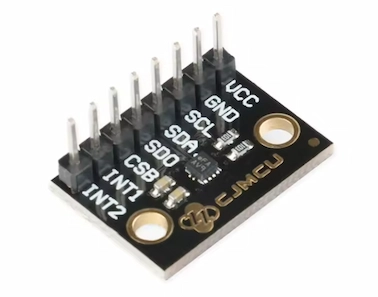
BMA400 Accelerometer Module
BMA400 3-axis ultra-low-power accelerometer module with I2C and SPI communication, motion detection, orientation sensing and step counting.
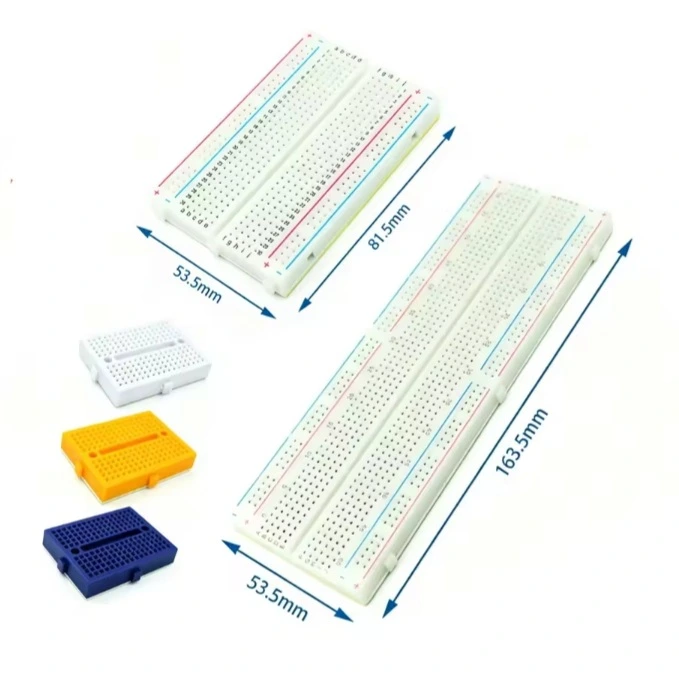
Solderless Breadboard
Reusable solderless breadboard for rapid prototyping of electronic circuits with Arduino, ESP32 and Raspberry Pi.
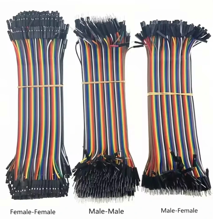
Jumper Wires
Jumper wires for breadboard prototyping with Arduino, ESP32, Raspberry Pi and other embedded development boards.